Intel
®
Server System SR9000MK4U Product Guide 169
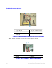
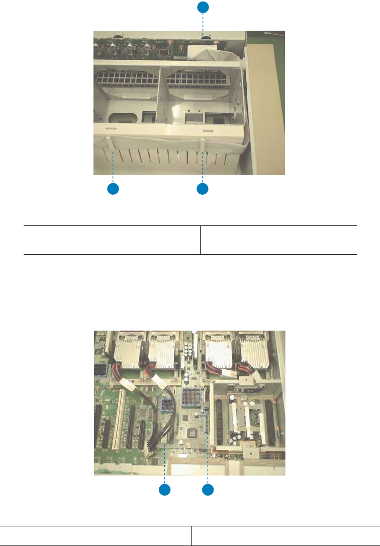
Figure 138. IDE Connection and Cable Routing
Note: The figure above shows the system with the fans removed.
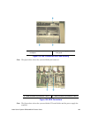
Figure 139. MVR Connectors
Note: The figure above shows the system with the PCI card divider and the power supply box
removed.
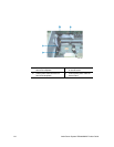
A. IDE connector on hard drive
backplane
B. IDE cable routing clips on air
flow guide
AF001436
A
B B
A. MVR connector for processors 1 and 2 B. MVR connector for processors 3 and 4
AF001437
A B


