30 Intel
®
Server System SR9000MK4U Product Guide
Hard Drive Population
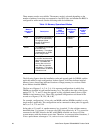
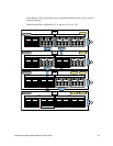
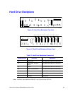
The on-board SAS controller is connected to four of the eight hard drives, drives 0
through 3. Hard drives 4 through 7 require the addition of an add-in SAS card.
Front Panel Board
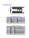
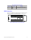
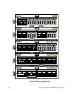
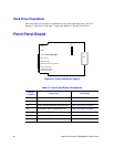
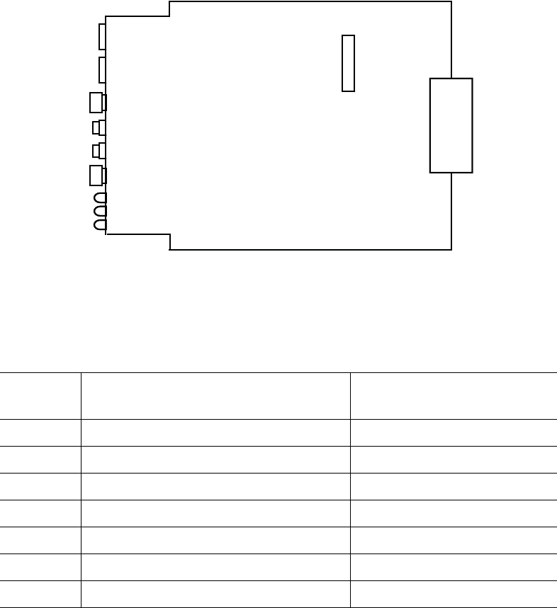
Figure 20. Front Panel Board Layout
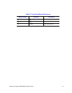
Table 16. Front Panel Board Components
Board
Location
Component Description
P1 Power Button, Power LED See “Front Panel” on page 5.
P2 Reset Button See “Front Panel” on page 5.
P3 SDINT (System Diagnostic Interrupt) Button See “Front Panel” on page 5.
P4 Identification Switch, Identification LED See “Front Panel” on page 5.
P5 Power Fault LED See “Front Panel” on page 5.
P6 Cooling Fault LED See “Front Panel” on page 5.
P7 General Fault LED See “Front Panel” on page 5.
AF001099
USB4
USB5
Power Switch / Power LED
Reset Switch
SDINT Switch
Identification Switch / ID LED
Power Fault LED
General Fault LED
DVD
HM
tch / Power LED
HM
Cooling Fault LED


