18 Intel
®
Server System SR9000MK4U Product Guide
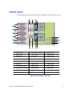
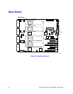
Main Board
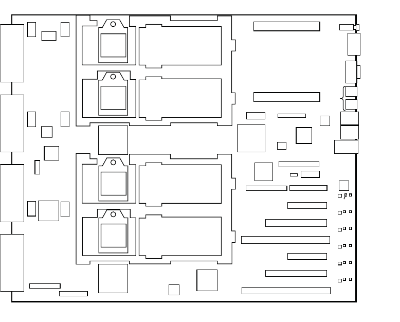
Figure 13. Main Board Layout
AF001095
Processor
Socket0
NDC0
NDC1
FAN0
VHDM0
PCI slot1
PCI slot2
PCI slot3
PCI slot4
PCI slot5
PCI slot6
PS0
COM
VGA
GbE
LAN0/1
LAN0
(Management)
USB2/3
USB0/1
ESB2
PXH
Main Board
LAN1
(KVM)
SAS
VGA
LAN
VHDM1
VHDM2
VHDM3
ID SW
FAN1
FAN2
FAN3
FAN4
FAN5
LAN
H8S
MVR0/1
MVR2/3
ATA
SAS
IPMB
DEBUG
KVM
XDP
FPGA
Processor
Socket1
Processor
Socket2
Processor
Socket3
PANEL
PS1
VRAM
Battery
PANEL PWR
P1
P2
P3
P4
P6
P5
P7
P8
P10
P12
P13
P9
E1
E2
E3
E4
E5
E6
C1
C2
C3
C4
C5
C6
C7
C8
C9
C10
C11
C12
C13
C14
C15 C16
C17 C18
C19
C20
C21
C22
C23
C24
C25
C26
C27
C28
C29
C30
C32
C33
P14
P15
P16
P17
P18
P19
P20
P21
P22
P23
P24
P25
P26
P27
P28
P29
P30
P31
P32
P33
P11
Super
IO
7SEG


