Intel
®
Server System SR9000MK4U Product Guide xxi
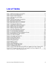
List of Tables
Table 1. Additional Information and Software .........................................................................viii
Table 2. Server Physical Specifications ....................................................................................1
Table 3. Chassis Feature Summary ..........................................................................................2
Table 4. SAS Hard Drive LED Details .......................................................................................7
Table 5. NIC LEDs ..................................................................................................................10
Table 6. 1390 W Power Supply Configuration ........................................................................12
Table 7. Main Board Components ...........................................................................................19
Table 8. Main Board External I/O Connectors .........................................................................21
Table 9. Main Board Internal I/O Connectors ..........................................................................21
Table 10. Configuration Restrictions .......................................................................................22
Table 11. Supported Processor Configuration ........................................................................23
Table 12. Memory Box Card Components ..............................................................................24
Table 13. Memory Box Card Connectors ................................................................................24
Table 14. Memory Operational Modes ....................................................................................26
Table 15. Hard Drive Backplane Connectors ..........................................................................29
Table 16. Front Panel Board Components ..............................................................................30
Table 17. Front Panel Board Connectors ................................................................................31
Table 18. Loosening the Hard Drive Backplane Screws .......................................................105
Table 19. Boot Maintenance Menu Options ..........................................................................132
Table 20. EFI Shell Commands ............................................................................................135
Table 21. Command Line Description ...................................................................................143
Table 22. Using Setup Screens .............................................................................................146
Table 23. Primary Setup Screens .........................................................................................146
Table 24. Main Setup Screen ................................................................................................147
Table 25. Processor Screen ..................................................................................................148
Table 26. Memory Screen .....................................................................................................148
Table 27. Devices Screen .....................................................................................................149
Table 28. Server Management Screen .................................................................................150
Table 29. COM1 Console Redirection ...................................................................................150
Table 30. Troubleshooting Guide ..........................................................................................153
Table 31. POST Codes Generated by the BMC and Logged at the Seven Segment LED ...171
Table 32. POST Codes Generated by SAL and Logged at the Seven Segment LED ..........177
Table 33. Error POST Codes Generated by SAL ..................................................................179


