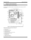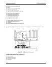
Jumpers and Connectors STL2 Server Board TPS
5-64
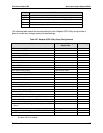
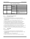
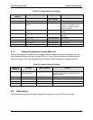
Table 5-1. Jumper Block 1J15 Settings
Jumper Pin
Numbers
Function Jumper Position What it does at system reset
1 - 2 CMOS clear
Open, Protect
Preserves the contents of CMOS
Closed, Erase Clears CMOS
3 - 4 Password protected
Open, Normal
Preserves the password
Closed, Disable Disables the password
5 - 6 Reserved
Open, Not Used
No function
7 - 8 Reserved
Open, Not Used
No function
9 - 10 BIOS Recovery Boot
Open, Normal
BIOS Recovery Boot disabled. Normal
operation.
Closed, Recovery Boot If this jumper is set, BIOS recovery will be
attempted from a bootable BIOS recovery
floppy diskette.
11 - 12 Spare
Closed, Spare
Provides a spare jumper
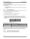
5.1.1.1 Clearing and Changing a Password
Clear and change a password as follows.
1. Power off the system, unplug the power cord, and remove the chassis panel.
2. Use needle nose pliers or your fingers to remove the spare jumper from pins 11-12 on
jumper block 1J15.
3. Reinstall the jumper on pins 3-4 (Password Disable) of jumper block 1J15.
4. Reinstall the chassis panel, plug in the power cord(s), and power on the system.
5. While waiting for POST to complete, press the F2 key to enter BIOS setup.
6. This automatically clears all passwords, provided you save and exit the BIOS setup.
7. Power off the system, unplug the power cord(s), and remove the chassis panel.
8. Remove the Password Disable jumper from pins 3-4 and store the jumper on pins 11-12.
9. Replace the chassis panel, plug in the power cord(s), and power on the system.
10. To specify a new password run the BIOS Setup Utility as described earlier in this section.
5.1.1.2 Clearing CMOS
Clear CMOS as follows.
1. Power off the system, unplug the power cord, and remove the chassis panel.
2. Use needle-nose pliers or your fingers to remove the spare jumper from pins 11-12 on
jumper block 1J15.
3. Position the jumper over pins 1-2 on jumper block 1J15.
4. Replace the chassis panel, plug in the power cable(s), and power on the system.


