


Installing the Hardware
Part No. 1H9613 June 1997 2-5
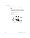
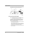
Making the Jumper Selections
JP1/JP2 Factory Settings (Both Jumpers On)
JP1 and JP2 are two small black jumpers near the right side in
the middle of the Network Interface Card. When the card is
shipped, each jumper is positioned across both sets of pins (ON).
This allows for both remote Telnet diagnostic monitoring and
normal operation/printing with 10BaseT.
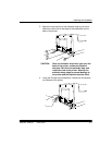
Cable Autodetection (Both Jumpers Off)
The connection autosensing feature automatically senses the
presence of a 10BaseT connection. If no 10BaseT connection is
sensed, a 10Base2 (BNC) connection is assumed. However,
Telnet capability is disabled.
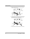
JP1/JP2 - selection of cable connection manually
Telnet and cable autodetection modes are the recommended use
of the JP1/JP2 jumpers.
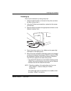
However, the cable type can also be selected manually. The
jumpers are positioned to match the locations of the two ports. If
you look at the Network Interface Card ports on the back of the
printer, the right port is for twisted pair, 10BaseT (RJ45) cabling.
The right jumper corresponds to that connector and is labeled
JP1. The left port is for ThinNet, 10Base2 (BNC) cabling. The left
jumper corresponds to that connector, and is labeled JP2.
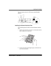
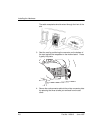
• For manual selection, lift the jumper for the appropriate
cable connector up and off the pin and then push it back
down over both pins. This specifies the particular connector
that will be in use.
NOTE: Move only the jumper for the cable connector type that
will be used. The other jumper must remain on one pin.