


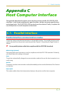

C.1. Parallel Interface
C-2
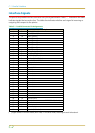
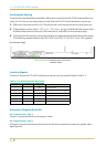
Interface Signals
The pins of the parallel interface connector carry the signals listed in Table C.1. Asterisks in the table
indicate signals that are active low. The table also indicates whether each signal is incoming or
outgoing with respect to the printer.
[ ]: Signal names in the Auto mode (IEEE 1284). In the Auto mode, these signals are bi-directional.
Table C.1. Parallel Connector Pin Assignments
Pin In/out Description
1In
Strobe* [nStrobe]
2In
Data 0 [Data 1]
3In
Data 1 [Data 2]
4In
Data 2 [Data 3]
5In
Data 3 [Data 4]
6In
Data 4 [Data 5]
7In
Data 5 [Data 6]
8In
Data 6 [Data 7]
9In
Data 7 [Data 8]
10 Out
Acknowledge* [nAck]
11 Out
Busy [Busy]
12 Out
Paper Empty [PError]
13 Out
On-Line (Select) [Select]
14 In
Auto-feed [nAutoFd]
15 —
Not connected
16 —
0V DC
17 —
Chassis GND
18 —
+5V DC
19 —
Ground return
20 —
Ground return
21 —
Ground return
22 —
Ground return
23 —
Ground return
24 —
Ground return
25 —
Ground return
26 —
Ground return
27 —
Ground return
28 —
Ground return
29 —
Ground return
30 —
Ground return
31 In
Ignored [nInit]
32 Out
Error*, returns error status if FRPO O2=2 [nFault]
33 —
—
34 —
Not connected
35 Out
Power Ready
36 In
Select In [NSelectIn]