


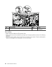
For access, remove these FRUs in order:
• “1010 Battery pack” on page 68
• “1020 Serial Ultrabay Enhanced device or blank bezel” on page 69
• “1030 Memory module slot cover” on page 70
• “1050 Hard disk drive or solid state drive” on page 72
• “1060 Keyboard” on page 74
• “1080 PCI Express Mini Card for wireless LAN” on page 78
• “1090 PCI Express Mini Card for wireless WAN or mSATA solid state drive” on page 80
• “1100 ExpressCard blank bezel or ExpressCard” on page 84
• “1120 Bluetooth daughter card” on page 88
• “1130 Backup battery” on page 89
• “1140 Smart card, dummy smart card and spacer” on page 90
• “1150 Speaker assembly” on page 91
• “1160 Thermal fan assembly” on page 92
• “1180 LCD unit” on page 96
• “1190 Base cover assembly” on page 99
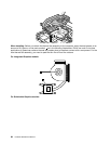
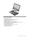
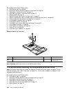
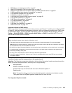
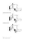
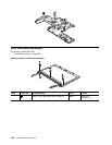
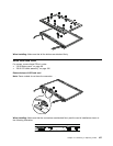
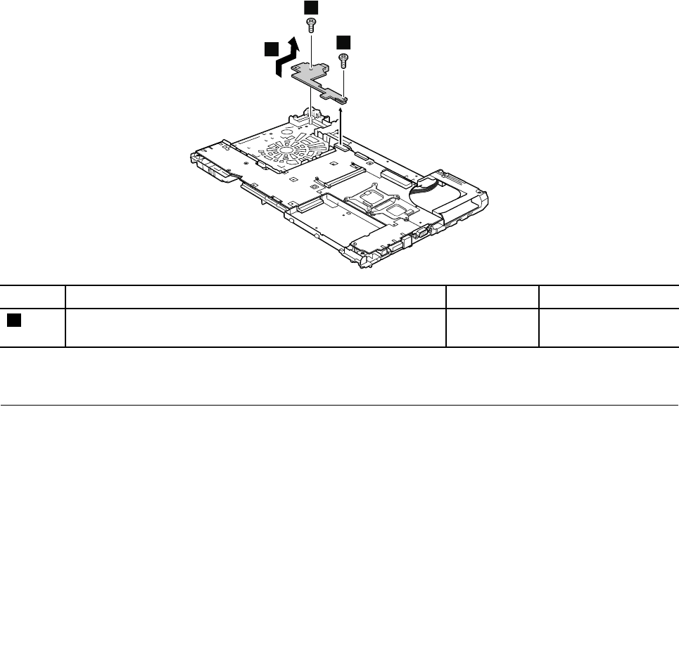
Removal steps of I/O sub card
2
1
1
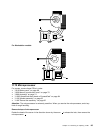
Step Screw (quantity) Color
Torque
1
M2 × 7 mm, wafer-head, nylon-coated (2) Silver
0.181 Nm
(1.85 kgf-cm)
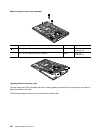
When installing: Make sure that the connector is attached rmly.
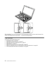
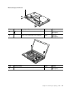
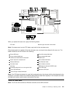
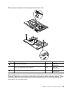
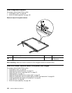
1210 System board assembly and magnesium structure frame
Note: The system board does not contain the Ethernet connector and the ac power connector. For the
Ethernet connector, see “1200 I/O sub card” on page 101
. The ac power connector is installed on the
magnesium structure frame.
For access, remove these FRUs in order:
• “1010 Battery pack” on page 68
• “1020 Serial Ultrabay Enhanced device or blank bezel” on page 69
• “1030 Memory module slot cover” on page 70
• “1040 Memory module (bottom slot)” on page 71
• “1050 Hard disk drive or solid state drive” on page 72
• “1060 Keyboard” on page 74
102 Hardware Maintenance Manual