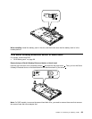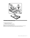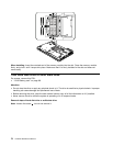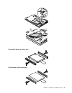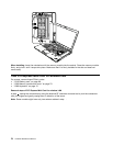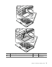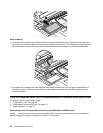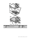
When installing: Make sure that the solid state drive connector or hard disk drive connector is attached
rmly.
1060 Keyboard
For access, remove these FRUs in order:
• “1010 Battery pack” on page 68
• “1030 Memory module slot cover” on page 70
Removal steps of keyboard
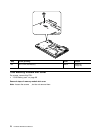
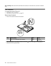
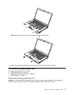
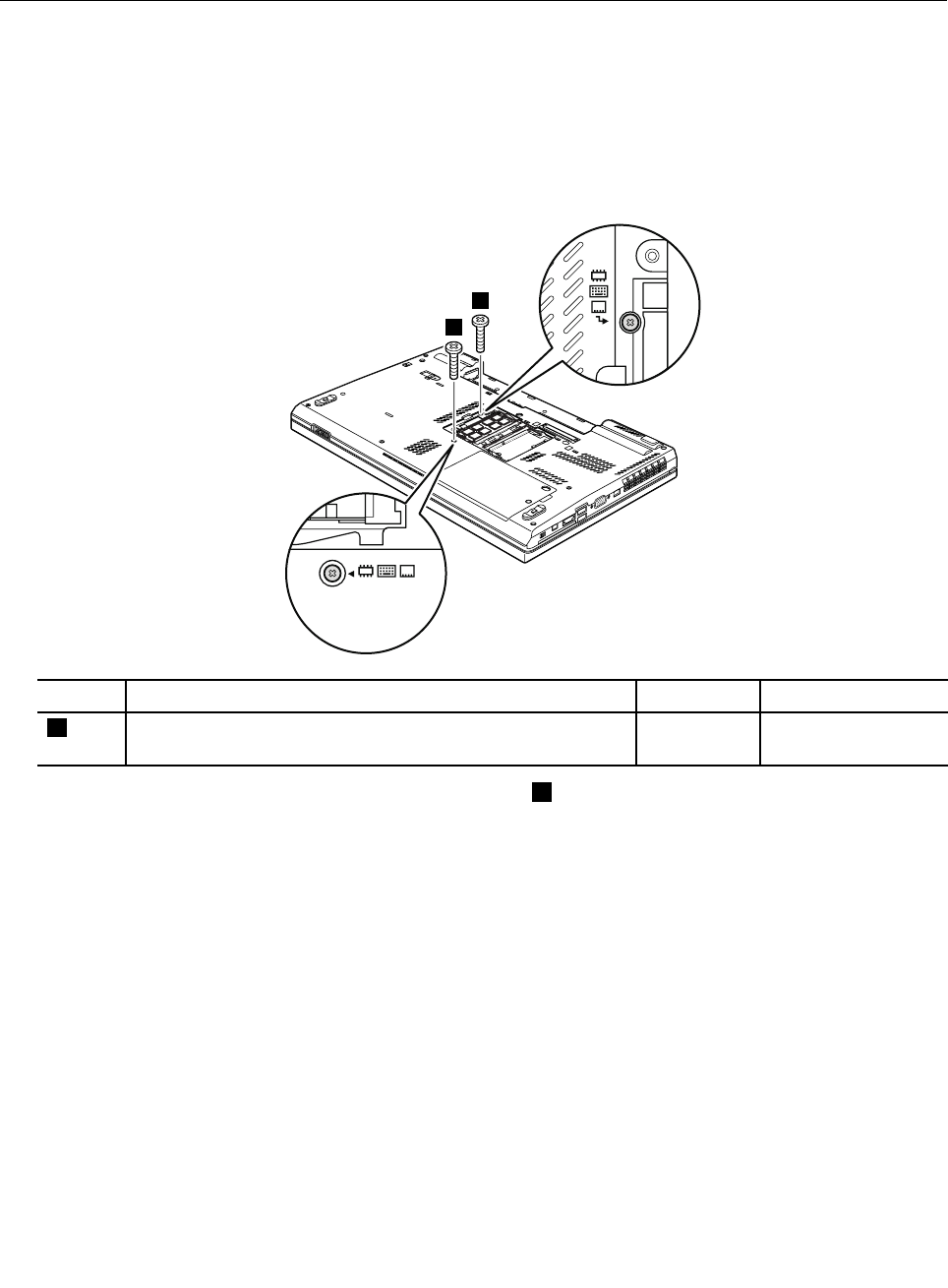
1. Remove the screws that secure the keyboard.
1
1
Step Screw (quantity) Color
Torque
1
M2 × 14 mm, wafer-head, nylon-coated (2)
Black 0.181 Nm
(1.85 kgf-cm)
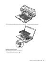
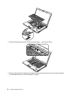
2. Press the keyboard in the direction shown by the arrow 2 until the front edge of the keyboard is
detached from the keyboard bezel.
74 Hardware Maintenance Manual


