


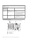
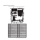
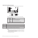
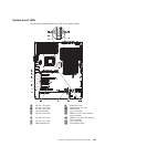
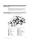
System-board switches and jumpers
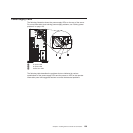
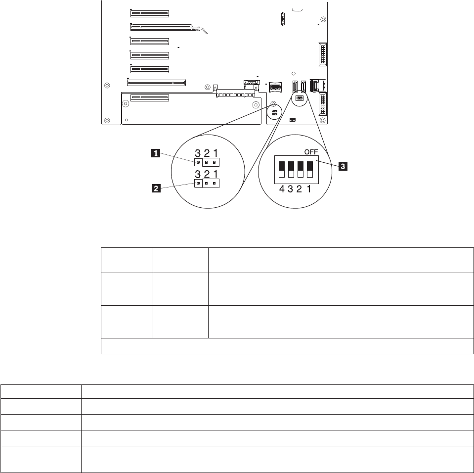
The following illustration shows the switches and jumpers on the system board.
See Table 9 and Table 10 for information about the switch and jumper settings.
Table 9. System-board jumpers
Jumper
number
Jumper
name Jumper setting
JP1 CMOS clear
v Pins 1 and 2: Normal operation (default).
v Pins 2 and 3: Clears CMOS memory.
JP6 UEFI boot
recovery
v Pins 1 and 2: Normal operation (default).
v Pins 2 and 3: Enable the UEFI recovery mode.
Note: If no jumper is present, the server responds as if the jumper is on pins 1 and 2.
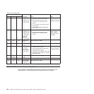
Table 10. System-board switch 6
SW 6 Switches Switch description
1 Reserved (default off)
2 Power-on password override when on. (default off)
3 Reserved (default off)
4 When this switch is off, the primary IMM firmware ROM page is loaded. When this switch is on,
the secondary (backup) IMM firmware ROM page is loaded. (default off)
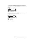
Notes:
1. Before you change any switch settings or move any jumpers, turn off the server;
then, disconnect all power cords and external cables. (Review the information in
Chapter 2, “Safety information,” on page 5.)
2. Any system-board switch or jumper blocks that are not shown in the illustrations
in this document are reserved.
144 ThinkServer TD200x Types 3719, 3821, 3822, and 3823: Hardware Maintenance Manual