


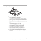

1. Touch the static-protective package that contains the system board to any
unpainted metal surface on the server; then, remove the system board from
the package.
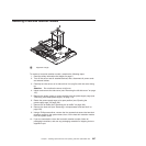
2. Hold the system board by the handles and insert the system board into the
chassis at an angle; then, slide it toward the rear of the server.
Note: Make sure that none of the server cables are caught under the system
board.
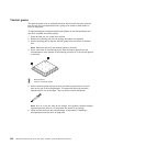
3. Press down on the retention modules; then, rotate the release lever toward the
rear of the chassis to secure the system board.
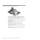
4. Install any of the following components that you removed from the system
board:
v Microprocessors and heat sinks (see “Installing a microprocessor and heat
sink” on page 220).
v DIMMs (see “Installing a memory module” on page 211).
v Extender card (see “Installing an extender card” on page 209).
v Adapters (see “Installing an adapter” on page 184)
v Battery (see “Installing the battery” on page 173).
5. Reconnect any cables to the system board that you disconnected during
removal (see “System-board internal connectors” on page 131 and “Internal
cable routing and connectors” on page 163).
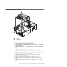
6. Install the fan-cage assembly (see “Installing the fan-cage assembly” on page
172).
7. Install the air baffle (see “Installing the air baffle” on page 170).
8. Return the power-supply cage to its closed position (see “Closing the
power-supply cage” on page 160).
9. Install the power supplies (see “Installing a hot-swap power supply” on page
175).
10. Install and lock the left-side cover (see “Installing the left-side cover” on page
158).
11. Reconnect the external cables and power cords; then, turn on the attached
devices and turn on the server.
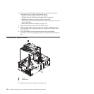
Completing the installation
To complete the installation, do the following:
1. Insert the bezel hinges into the slots on the server chassis and close the bezel
(“Closing the bezel media door” on page 156 and “Closing the bezel” on page
151).
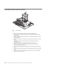
2. Position the left-side cover over the server.
3. Place the bottom edge of the cover onto the bottom edge of the server.
4. Rotate the top edge of left-side cover toward the server; then, press down on
the cover handle until it clicks into place (“Installing the left-side cover” on page
158).
5. Rotate the bezel to its fully closed position.
6. Using the supplied key, lock the left-side cover and bezel.
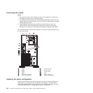
7. Connect the cables and power cords. For more information, see “Connecting
the cables” on page 234.
Chapter 7. Installing optional devices and replacing customer replaceable units 233