


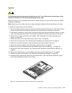
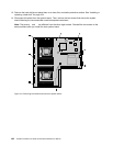
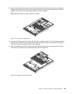
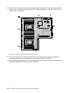
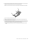
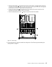


• Route the signal cables 1 through the left inner side of the chassis. The signal cables include the
mini-SAS to mini-SAS signal cable, the front panel cable, the front panel USB cable, the diagnostic
module cable, and the SATA signal cable for the optical drive.
• Connect the power cable 2 for the optical drive to the optical drive power connector on the
backplane and properly route the cable in the chassis.
• Route the backplane power cable 3 through the right inner side of the chassis.
Figure127. Cable routing
3. If the cooling shroud is removed, reinstall the cooling shroud. See “Removing and reinstalling the
cooling shroud” on page 73.
Chapter 6. Installing, removing, or replacing hardware 155