


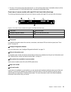
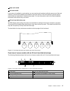
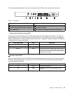
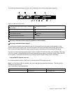
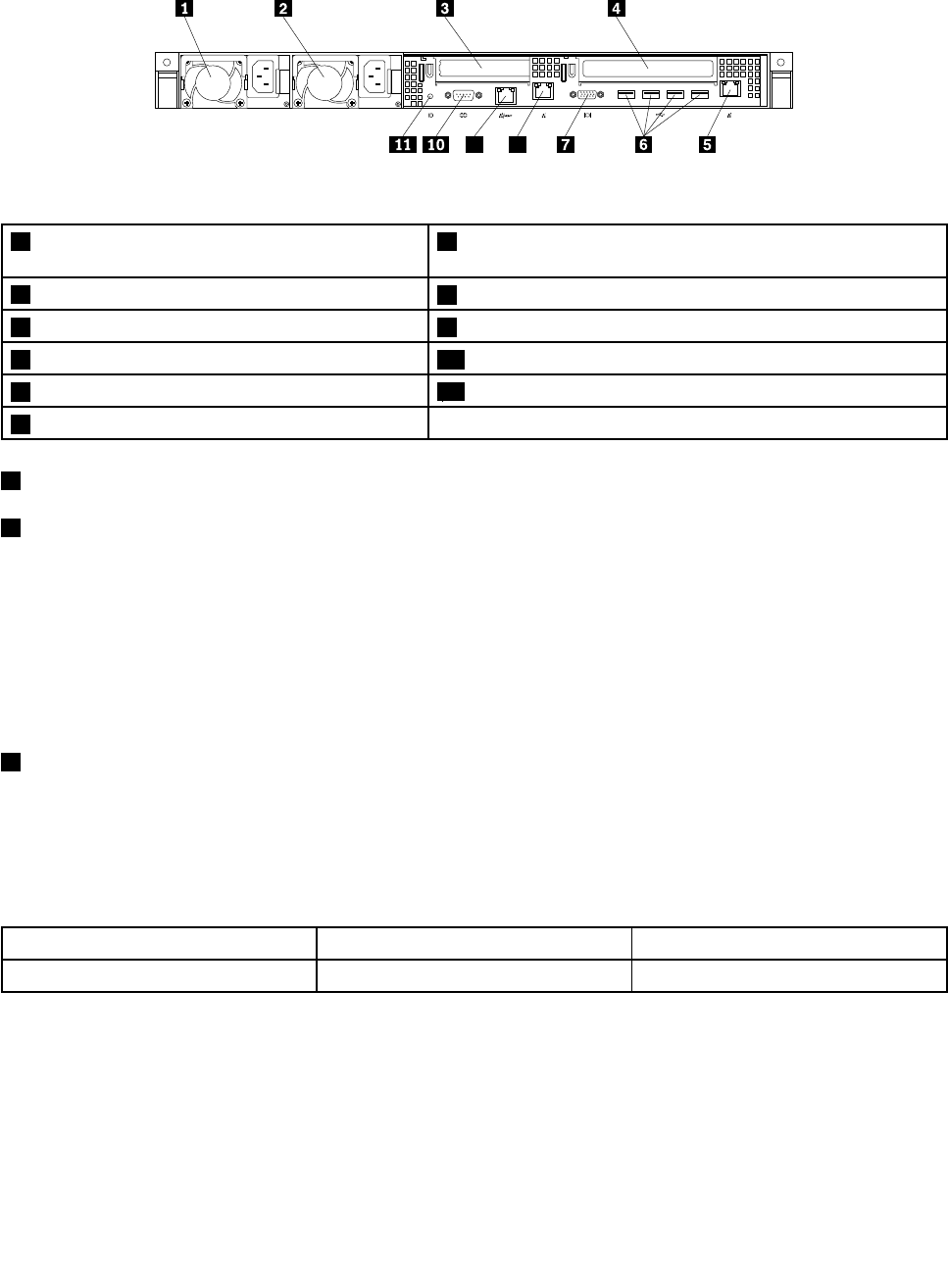
The following illustration shows the rear view of the server with two hot-swap power supplies.
1
0
MGMT
ID
8
9
2
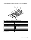
Figure13. Rear view of the server
1 Hot-swap redundant power supply 2 (available in
some models)
7 VGA DB-15 connector
2 Hot-swap redundant power supply 1
8 Ethernet connector 1 (RJ-45)
3 Low-prole PCI Express card slot 9 Ethernet connector 0 (RJ-45) (for system management)
4 PCI Express card slot 10 Serial port
5 Ethernet connector 2 (RJ-45)
11 ID LED
6 USB connectors (4)
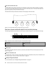
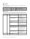
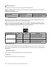
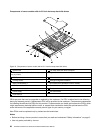
1 Hot-swap redundant power supply 2 (available in some models)
2 Hot-swap redundant power supply 1
The hot-swap redundant power supplies help you avoid signicant interruption to the operation of the
system when a power supply fails. You can purchase a hot-swap redundant power supply option directly
from Lenovo and install the power supply to provide power redundancy without turning off the server.
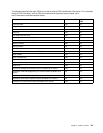
On each hot-swap redundant power supply, there is a status LED near the power cord connector. When the
LED is lit in green, it indicates that the hot-swap redundant power supply is working correctly. When the LED
is lit in amber, it indicates that the hot-swap redundant power supply is likely to fail or has failed.
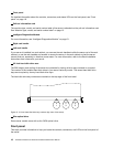
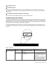
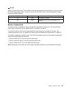
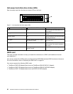
3 Low-prole PCI Express card slot
It is recommended to attach a RAID card to the low-prole PCI Express card slot.
Note: If a ThinkServer HBA is available, refer to its user guide for detailed information. The user guide is
available for download at:
http://www.lenovo.com/UserManuals
Physical link width Negotiable link width
Supported card length and height
x8 x8, x4, x2, x1
Low-prole card
Chapter 3. Product overview 23