


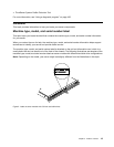
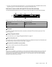
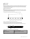
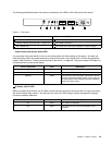
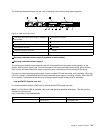
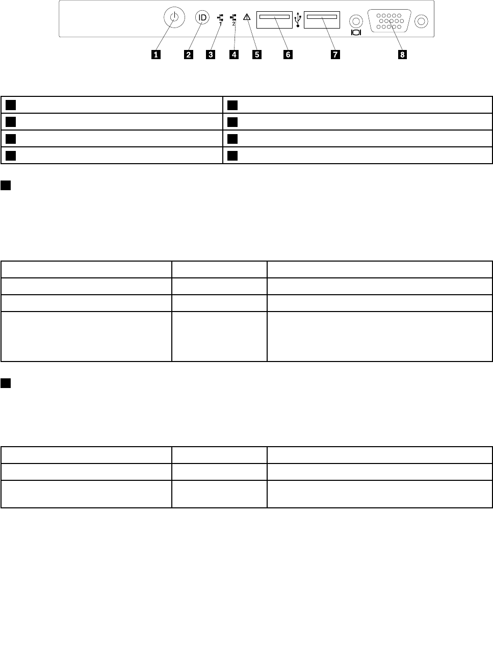
The following illustration shows the controls, connectors, and LEDs on the front panel of the server.
ID
Figure11. Front panel
1 Power switch with power status LED
5 System error LED
2 ID button with ID LED
6 Front USB connector 1
3 Network Interface Controller (NIC) 1 status LED 7 Front USB connector 2
4 NIC 2 status LED 8 Front VGA DB-15 connector (available in some models)
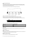
1 Power switch with power status LED
You can press the power switch to turn on the server when you nish setting up the server. You also can
hold the power switch for several seconds to turn off the server if you cannot turn it off from the operating
system. See Chapter 4 “Turning on and turning off the server” on page 49
. The power status LED helps you
to determine the current power status.
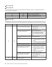
Power status LED
Color
Description
On Green
The server is on.
Off
None
The server is off.
Blinking
Green The server is in ACPI S1 mode, which also is known
as Power On Suspend (POS) mode. In this mode, the
microprocessor is not working while other hardware
devices are still working.
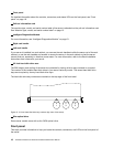
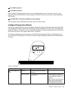
2 ID button with ID LED
When you press the ID button, the ID LEDs on both the front and rear of the server are lit to help you locate
the server among other servers. You also can turn on the ID LEDs using a remote management program
for server presence detection.
ID LED
Color
Description
On
Blue
The system is identied.
Off
None The ID LED is not in use or the system is not
identied.
Chapter 3. Product overview 19