


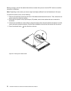
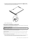
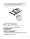
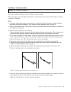

3. Note the orientation of the cooling shroud and then place it above the server so that the tabs on both
sides of the cooling shroud are aligned with the corresponding holes or gaps in both sides of the
chassis. Then, lower the cooling shroud into the chassis until it snaps into position.
Note: If necessary, gently press the cooling shroud on both sides so that the tabs on the cooling shroud
completely engage with both sides of the chassis.
ID
Mem
CPU
PSU
Figure39. Reinstalling the cooling shroud
4. Reinstall the server cover and reconnect cables to the server. For more information, refer to “Reinstalling
the server cover and reconnecting cables” on page 154.
Installing or removing a memory module
This topic provides instructions on how to install or remove a memory module.
Note: The memory modules are extremely sensitive to ESD. Ensure that you read and understand “Handling
static-sensitive devices” on page 68 rst and carefully perform the operation.
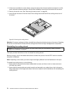
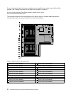
Memory module installation rules
Your server has 20 memory slots.
• Each slot supports 4 GB, 8 GB, and 16 GB DDR3 RDIMMs.
• Your server supports up to 12 normal RDIMMs when one microprocessor is installed and up to 20
RDIMMs when two microprocessors are installed.
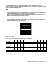
• The minimum system memory is 4 GB (only one microprocessor installed and only one 4 GB memory
module installed in the CPU1 DIMMA1 slot).
• The maximum system memory for RDIMMs is 320 GB (two microprocessors installed and one 16 GB
RDIMM installed in each of the 20 memory slots).
Chapter 6. Installing, removing, or replacing hardware 75