


2-78 Service Manual
4069-XXX
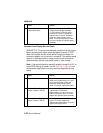
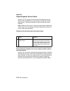
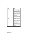
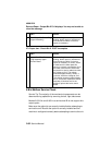
990 Service - BIN X
FRU Action
1 D.C. Motor
Mechanical Linkage
Assembly
Check the DC motor cable
connector to be sure it is correctly
installed at J4 on the output
expander option board. If correct,
disconnect J4 from the option
board and check the resistance of
the motor on the cable connector:
J4-1 to J4-2: measures between
115 and 135 ohms. Also check J4-
1 and J4-2 to the motor case for
shorts. If either the resistance is
incorrect or a short is found,
replace the motor/mechanical
linkage assembly.
Note: If the DC motor is shorted, it
may also be necessary to replace
the control board.
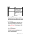
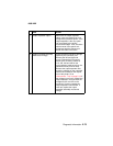
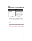
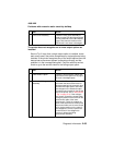
2 Output Expander Control
Board
Disconnect the motor cable J4
and check the voltages at J4 on
the board.
Note: Use caution not to short to
adjacent pins on the connector.
J4-1 (Motor Idle) +24 V dc
J4-2 (Motor Idle) +24 V dc
J4-5 (Motor Idle) +5 V dc
J4-6 (Motor Idle) +5 V dc
If any of the voltages are incorrect,
replace the control board. If the
voltages are correct, replace the
DC motor/mechanical linkage
assembly.