


Diagnostic Information 2-33
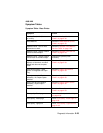
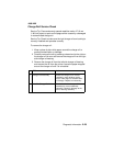
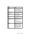
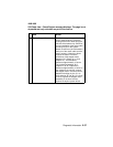
4069-XXX
3 +5 V dc at any Option
Connector
Check for +5 V dc on any of the
option connectors. The easiest to
access is the envelope feeder
connector located behind the lower
front door. If +5 V dc is present at
any of the connectors, go to step 9. If
+5 V dc is not present, go to step 4.
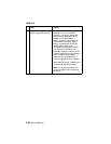
4 +5 V dc at the controller
board test point
Check for +5 V dc at the +5 V dc test
pad located on the controller board.
If correct, go to step 9.
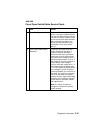
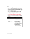
5 +5 V dc at the engine board
Test Poi nt
Check for +5 V dc at the +5 V dc test
point on the engine board. If correct,
replace the engine board. If
incorrect, go to step 6.
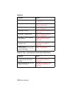
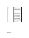
6 LVPS Fuse F1 Remove the LVPS from the printer
and check fuse F1. Replace the fuse
if the fuse is blown.
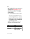
7 LVPS Fuse F1 - Continues
to blow after LVPS installed
in the printer.
Replace fuse F1 if necessary. Turn
the LVPS on/off switch Off and
connect the AC line cord and turn
the LVPS On.
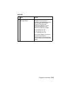
CAUTION: Before checking fuse F1
turn the LVPS Off and disconnect
the AC line cord. Check fuse F1. If
the fuse is blown, replace the LVPS.
8 LVPS Remove the LVPS from the machine.
CAUTION: Before making any
measurements on the LVPS output
connector, observe all necessary
safety precautions before applying
AC power. Measure the voltage on
LVPS output connector CN3. The
voltage measures +5 V dc. If
incorrect, replace the LVPS.
FRU Action