


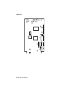
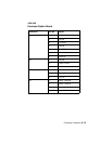

Connector Locations 5-13
4069-XXX
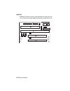
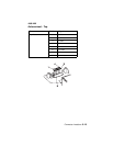
Note: A 902 service error may display if the jumpers are not
correctly installed.
• Models 010 and 01n have a jumper on J10 between the center
pin and pin 5.
• Models 212 and 21n have a jumper between the center pin and
pin2 of J8, a jumper between the center pin and pin 4 on J9 and
a jumper between the center pin and pin 5 of J10.
• Models 414, 41b, 41L and 41n have a jumper between the
center pin and pin 2 of J8 and a jumper between the center pin
and pin 3 of J9.
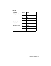
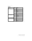
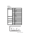
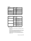
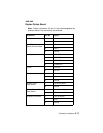
J5 Autoconnect
BTM/FNT
1+24 V dc
2 Ground
J6 Engine Board 1 N/A
J7 Controller Board 1 N/A
J11 INA 1 1 N/A
J12 INA 2 1 N/A
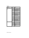
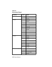
Connector
Jumper
Position
Signal
J8 ID-1 1 0 V dc (Gnd) center pin
to top pin of J8
2 + 5 V dc center pin to
bottom pin of J9
J9 ID-2 3 0 V dc (Gnd) center pin
to top pin of J9
4 +5 V dc center pin to bot-
tom pin of J9
J10 ID-3 5 0 V dc (Gnd) center pin
to top pin of J10
6 +5 V dc center pin to bot-
tom pin of J10
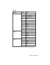
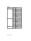
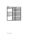
Connector Pin No. Signal