


26
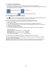
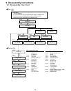
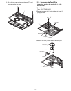
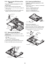
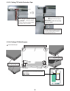
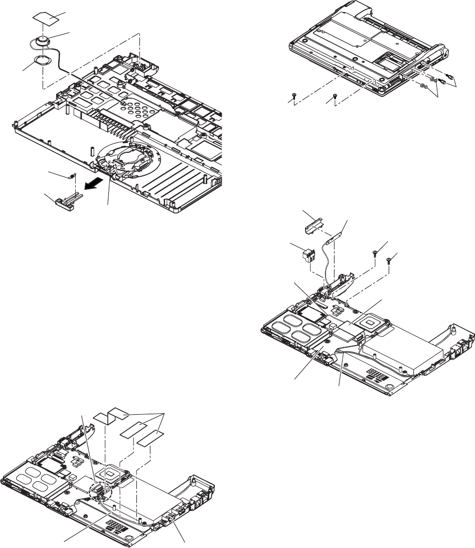
9.2.8. Removing the Main Board
Preparation : perform the section 9.2.1., 9.2.2.
and 9.2.4. first.
1. Remove the 1 screw (I ), 1 screw (J), 2 screws (K)
and 2 screws (L ).
Screw (I ) : DXQT2+E10FNL (N10)
Screw (J) : DXQT2+D4FNL (N9)
Screw (K) : DFHE5035ZB (N2)
Screw (L) : K1YE50000022 (N1003)
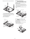
2. Remove the 2 screws (M).
Screw (M) : DXQT2+E6FNL (N12)
3. Remove the modem cable from the MDC modem.
4. Remove the side cover (L) from the bottom case.
5. Remove the DC jack holder on the DC-IN jack.
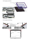
DC Jack
Holder
Side Cover (L)
Antenna Board (L)
Screw (N)
Screw (N)
Main Board
LAN Cable
Modem Cable
Tape
Screw ( I )
Screw (J)
Screw (K)
Screw (L)
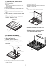
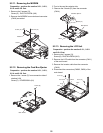
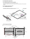
9.2.6. Removing the LCD Knob and the
Speaker
Preparation : perform the section 9.2.1., 9.2.2.
and 9.2.4. first.
1. Remove the latch spring from the top case.
2. Remove the hook of the LCD knob from stopper rib
of the top case.
3. Peel off the4.Peel off the tape on the speaker and
speaker ring and then remove the speaker.
Speaker Box
Speaker
Speaker
Ring
Location of the Spring
Latch
Spring
LCD Knob
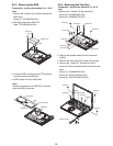
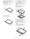
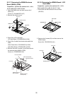
9.2.7. Removing the USB Board
Preparation : perform the section 9.2.1., 9.2.2.
and 9.2.4. first.
1. Peel off the tapes and RJ cable sheet for clamp the
USB cable.
Tape : TPD-X0033A (S1001)
RJ Cable Sheet : DFHR3C13ZA (K53)
2. Remove the connector (CN23) on the main board.
3. Remove the USB board from the bottom case.
CN23
Tape
2-Port USB Board
USB Cable