


28
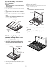
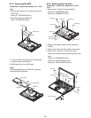
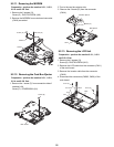
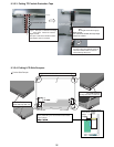
9.2.11. Removing the MODEM
Preparation : perform the section 9.2.1., 9.2.2.,
9.2.4. and 9.2.8. first.
1. Remove the 2 screws (O).
Screw (O) : DXQT2+D25FNL (N8)
2. Remove the MODEM from main board connector
(CN18) as vertical.
Screw (O)Screw (O)
CN18
Modem
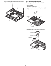
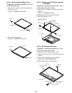
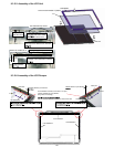
9.2.12. Removing the Card Bus Ejector
Preparation : perform the section 9.2.1., 9.2.2.,
9.2.4. and 9.2.8. first.
1. Remove the 1 screw (P) from connection side of
wireless LAN.
Screw (P) : DFHE5025XA (N1)
2.Turn to the card bus ejector side.
3. Remove the 2 hooks (G) from the connector
(CN14).
Main Board
Screw (Q)
Main Board
Card Bus Ejector
Hook (G)
CN14
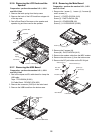
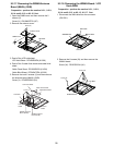
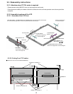
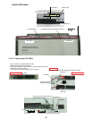
9.2.13. Removing the LCD Unit
Preparation : perform the section 9.2.1., 9.2.2.
and 9.2.4. first.
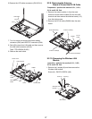
1. Remove the 2 screws (Q).
Screw (Q) : DXQT26+D5FNL (N13)
2. Remove the LCD cable from the connector (CN11)
of the main board.
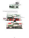
3. Remove the inverter cable from the connector
(CN10).
4. Disconnect the connectors (CN603, CN28) of the
main board.
CN10
CN603
CN28
CN11
Screw (Q)
LCD Cable
Screw (Q)