


45
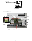
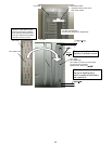
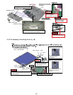
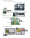
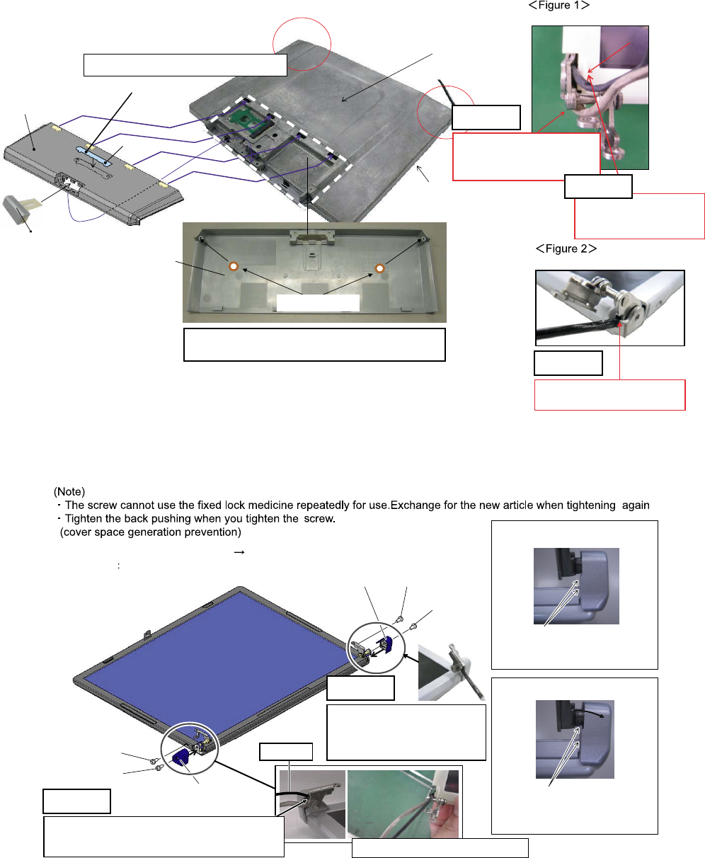
Engages with LCD FRONT
goods which have prepared
LCD REAR
Refer to Figure 1
Refer to Figure 2Refer to Figure 2
Multiply the fingernail
in 16 all places surely
SIMM COVER WAN
Insertion
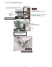
Cable drawing out route
The LCD signal line is
drawn out between
wearing FRONT and REAR
The touch panel cable is
drawn out between
FRONT and HINGE.
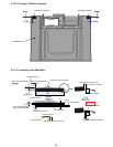
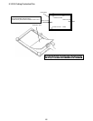
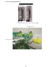
ANTENNA COVER
ANTENNA COVER
ANTENNA COVER is affixed and SPACER CU is
affixed on the boss before the installation
Lock engagement
Cable drawing out route
Safety work
SPACER CU
The fingernail in four places is inserted
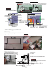
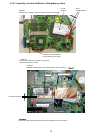
PANASONIC LABELPANASONIC LABEL
Safety work
Safety work
The cable is drawn out
between FRONT and REAR.
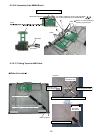
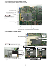
Hinge cover installation OK figure
Hinge cover installation NG figure
Hinge Cover R
Screw
Screw
Screw
Screw
The order of tightening screw:a b
Screw DRHM0076ZA
a
a
b
b
Hinge Cover L
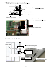
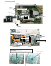
The cover externals and the
Front rib are parallel
(agreement).
The cover externals are not
parallel to the Front rib.
Inclines.
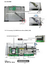
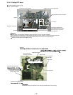
The cable is processed under the axis .
It is confirmed that the cable does not narrow
between cabinets.
The TP cable passes on the axis
TP cable
Safety work
The cable is processed under
the axis . It is confirmed that
the cable does not narrow
between cabinets.
Safety work
9.3.2.19. Assembly of the Hinge Cover (L), (R)