


60
9.3.5. Assembly knowhow of the Bottom Case
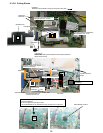
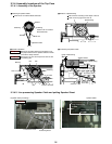
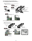
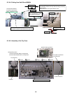
9.3.5.1. Setting Antenna Board and Line processing (1)
Places between the
Bottom Case and installs
Process Antenna Cable (L) which remained after installing Antenna Board (L)
in the Bottom Case as shown in the figure below.
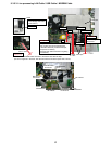
DC-IN is installed in bottom
Ferrite sheet is
processed in board.
The load is not put on
the terminal of DC-IN.
Processes with the boss between ribs
Processes to the ditch
of the Bottom Case
It is confirmed that the terminal
becomes the immediate truth it below
Antenna Cable (L)
Antenna Board (L)
Boss
Bottom Case
Wiring of Antenna Cable (L)
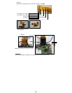
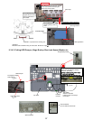
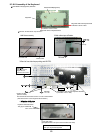
Screw N12-2
Screw N12-1
DC-IN is installed in the Bottom Case
It is confirmed that the terminal becomes straight
Safety work
Safety work
Safety work
Safety work
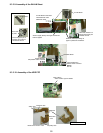
DXQT2+E6FNL
DC-IN
Holder
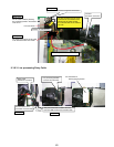
Hook is hooked to
the Bottom Case
Hook is hooked to
the Bottom Case
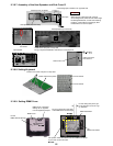
The top side is closed while hooking
the hook below on the Bottom Case
Antenna Cover (L)
Assembly the Antenna Cover (L)
Antenna Cover (L) installation
completion Chart
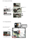
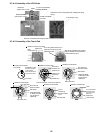
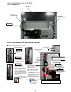
DC-IN Holder
Installation
LCD Cable Sheet
Confirmation
It is confirmed that the terminal becomes straight, installs the DC-IN Holder, and affixation LCD Cable Fix Shee
Safety work
It is confirmed that Ferrite sheet
has been inserted under the board.
Safety work
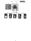
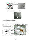
9.3.5.2. Assenbly of the Antenna Cover (L)