


58
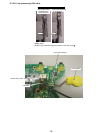
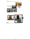
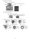
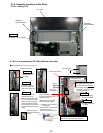
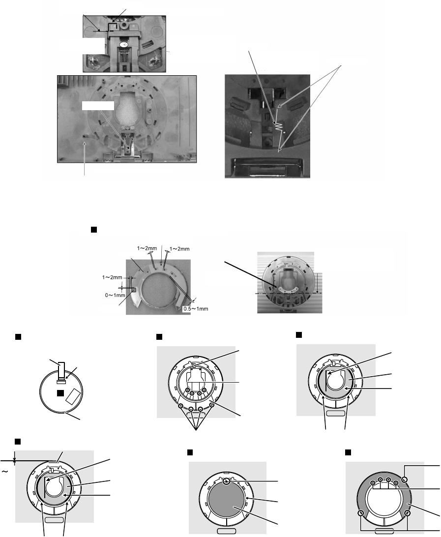
9.3.4.4. Assembly of the LCD Knob
Difference match
(Gap 0.5mm or less)
Rib match
(Gap 0.5mm or less)
Sheet
Put on the case before
inserting the knob
LCD Knob
The hook is inserted while doing the slide.
The spring is hung.
KNOB and SRING
are fixed
Confirm the LCD knob operates after installing the spring.
Spring
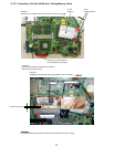
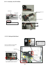
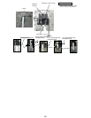
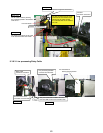
9.3.4.5. Assembly of the Touch Pad
The spring installation part opening
edge is matched and put between
positional decision pins.
It is a thing which does not run
aground in the pin as for the
PAD button seat.
Hook
Insert Hooks
PAD Cover
Affixation of PAD Cover
It is confirmed that
all LED lenses fit
in the hole of the
PAD cover.
Pin for
positioning
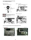
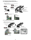
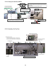
The Touch PAD
is put
Affixation of Touch PAD
Touch PAD
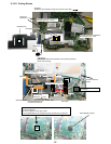
Touch PAD
FFC (PAD)
Insertion of FFC(PAD)
Affixation of PAD Cover Tape
FFC(PAD)
is insert-
ed in the connector
in the direction
where the reinforce-
ment board is seen.
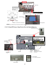
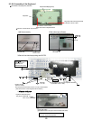
This line must
become vertical.
Sets in the dent.
PAD Sheet
Affixation of PAD Sheet
PAD Cover
Tape
PAD
Cover Tape
After PAD Sheet
is affixed, the flak-
ing off paper is
peeled off.
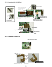
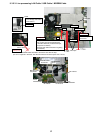
0 1mm
Two sided tape
This line must
become vertical.
Sets in the dent.
PAD Sheet
Affixation of PAD Sheet
After PAD Sheet
is affixed, the flak-
ing off paper is
peeled off.
PAD Button
Hook is inserted in a top case.(4 places)
Installation of PAD button
To install on
the ditch, the
gasket is put.
Inserts in the
positioning
pin.