


Figures
figure description . . . . . . . . . . . . . . . . . . . . . . . . . . . . . . . . . . . . . . . .page
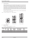
1-1 System Configurations. (N+1 = added redundancy) . . . . . . . . . . . 1-2
2-1 Installation Drawing, 7 kVA Inverter System . . . . . . . . . . . . . . . . .2-2
2-2 Front View, 7 kVA, System Component Description . . . . . . . . . . . .2-3
2-3 Line To Neutral Inverter Receiver Junction Box . . . . . . . . . . . . . . .2-5
2-3a Static Switch Section - Input and Output Wiring . . . . . . . . . . . . . . .2-6
2-4 EMI and Busbar VAC Configurations . . . . . . . . . . . . . . . . . . . . . . .2-7
2-5 Line To Neutral Setup Screen . . . . . . . . . . . . . . . . . . . . . . . . . . . .2-9
2-6 Line To Line Inverter Receiver Junction Box . . . . . . . . . . . . . . . . .2-12
2-6a Static Switch Section - Input and Output Wiring . . . . . . . . . . . . . .2-13
2-7 Line To Line Setup Screen . . . . . . . . . . . . . . . . . . . . . . . . . . . . . .2-15
2-8 Inverter Module . . . . . . . . . . . . . . . . . . . . . . . . . . . . . . . . . . . . .2-16
2-9 S4 Inverter Components . . . . . . . . . . . . . . . . . . . . . . . . . . . . . . .2-18
3-1 Redundant Microprocessor Component Location . . . . . . . . . . . . . .3-5
Tables
table description . . . . . . . . . . . . . . . . . . . . . . . . . . . . . . . . . . . . . . . .page
1-1 Inverter System Characteristics . . . . . . . . . . . . . . . . . . . . . . . . . . .1-2
1-2 Inverter Module Dimensions . . . . . . . . . . . . . . . . . . . . . . . . . . . . .1-3
1-3 S4 AC Output Current Ratings (with resistive load) . . . . . . . . . . . .1-3
1-4 S4 Receiver Cabinet Mechanical Dimensions and Weights . . . . . .1-4
2-1 Line To Neutral Units Suggested Circuit Breaker Ratings . . . . . . . .2-4
2-2 Line To Neutral Units Suggested DC Circuit Breaker Ratings . . . . .2-5
2-3 Line To Line Units Suggested Circuit Breaker Ratings . . . . . . . . .2-11
2-4 Line To Line Units Suggested DC Circuit Breaker Ratings . . . . . .2-12
2-5 Alarm Connections . . . . . . . . . . . . . . . . . . . . . . . . . . . . . . . . . . .2-17
3-1 Spare Parts and Kits . . . . . . . . . . . . . . . . . . . . . . . . . . . . . . . . . . .3-4
3-2 Troubleshooting table . . . . . . . . . . . . . . . . . . . . . . . . . . . . . . . . . .3-7
Contents
3.5 to 21 kVA N+1 Inverter
page c —iv