


2.4 Wiring Connections Line to Neutral Units
Note: For Line to Line units please skip to section 2.7, page 2—10.
2.4.1 Grounding
For safety and proper operation of the unit, including maximum attenuation of electrical noise, suitable grounding is
required. A separate grounding electrode conductor should be connected from the safety ground (GND) terminal to
a nearby grounding electrode, and should be sized per National Electrical Code Article 250-94. The grounding elec-
trode should be grounded structural metal, a metal water pipe, or a suitable ground rod (National Electrical Code
250-26). The grounding electrode should be as near as possible to the unit. The S4 will accommodate two 1/0
gauge wire. Customer provides grounding system.
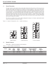
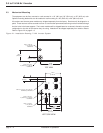
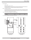
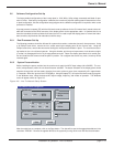
Move the receiver cabinet to its intended location, using one of the suggested handling methods. After it is in its
final position, remove the blank panels from the front of the receiver cabinet. Blank panels are supplied with the
unit so as to prevent damage to the unit during shipment. Remove these blank panels, but do not discard them.
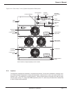
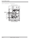
Remove top cover panel on the receiver’s static switch (cover of the panel with two fans) for access to the wiring
area. The connections to be made are the DC input connections, load connections, AC input connections, and
optional remote alarm connections. The connection terminals and busbars are located at the static switch area,
which is in the center of the receiver cabinet. For safety, the DC safety ground connection should be connected
first, then DC positive (+) connection made next, then the DC negative (-) last.
2.5 Input and Output Cable Connections
2.5.1 AC Input Circuit Breaker
CAUTION: For Line to Neutral units 64074, 64144, and 64214 only.
WARNING: If utility line voltage is connected to the system, an appropri-
ately rated AC circuit breaker MUST be installed between the
supplying AC source and the inverter plant. Installation must
comply with local/national electrical installation requirements.
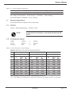
Table 2-1: Line To Neutral Units Suggested Circuit Breaker Ratings.
Inverter rating 7 kVA 14 kVA 21 kVA
AC breaker rating 120VAC 80A 150A 225A
240VAC 40A 80A 125A
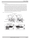
CAUTION: In applications with AC Input to the inverter, before connect-
ing the AC Input, remove the green bonding Jumper wire that
is connected between the Neutral (TB4) to ground. The bond-
ing wire is used for applications without AC Input, in Line to
Neutral units only.
Installation & Operation - Line to Neutral
3.5 to 21 kVA N+1 Inverter
page 2 — 4