


Installation & Operation - Line to Neutral
page 2 — 7
Owner’s Manual
2.5.4 Connections
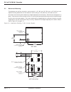
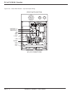
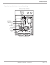
All DC input connections are made through the knock-outs, located in the top or left side panel. Refer to Figure 2-
1. Make sure that the upstream source DC circuit breaker and AC circuit breaker (if applicable) supplying the invert-
er are in the off (or open) position. DC input power cables should be sized such that the maximum voltage drop
between inverter busbar terminals and battery terminals is less than 1.0 volt at the breaker current rating. See Table
2-2 for CB breaker rating verses kVA rating. The inverter can accommodate three positive wires and three nega-
tive wires up to 4/0. Two 3/8” hole lugs, compression type with hole spacing of 1” should be used. All ground con-
nections should be made first, then positive (+) DC input cable should be connected, then the negative (-) connec-
tion last. The DC input landings are marked (+) and (–). Insert the input DC power cable through the selected top
or side panel knock-out. Connect the positive (+) cable to the lower terminal connection and the negative (–) cable
to the upper terminal connection landing. The 14 kVA and 21 kVA inverter require the super flexible (fine strand)
wire, which is installed with an optional Maintenance Bypass unit, and with an optional Junction Box that is mount-
ed to the back side of the Inverter receiver (14kVA and 21 kVA only). See Figure 2-3.
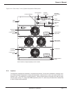
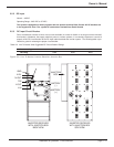
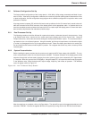
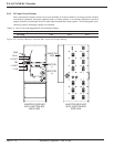
Figure 2-4: EMI and Busbar VAC Configurations.
Neutral Wire
AC Line Output Stud
110-120VAC Configuration
Neutral Wire
220-240VAC Configuration
BUSBAR
EMI
Filter
EMI
Filter
BUSBARS
Neutral Output