


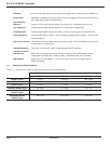

Efficiency 85% minimum, 88% typical (on-line mode); 97% typical (off-line mode) at full kVA/Watt load.
Power Factor Rated kVA is available over a power factor range of 0.6 lagging to 0.6 leading at nominal volt-
age. Watt rating should not be exceeded.
Total Harmonic
Distortion Less than 1% for linear load conditions, 3% maximum for crest factor loads up to 3:1.
Line Regulation System output voltage variation, less than 1% over the DC voltage range.
Load Regulation System output voltage variation, less than 1% from zero to full load at nominal DC input.
Output Frequency User-selectable, 50Hz or 60Hz. Free run frequency stability shall be within +/-0.02% of the
selected frequency.
Short Circuit Current (SCC)300% minimum of rated load current for four cycles. A SCC is defined as a current that
exceeds 150% of rated current.
Overload Capability Continuous overload up to 108% of rated VA/watts at 50°C maximum.
Transient Deviation
and Recovery Within 20% of average value for any change in output current or step change in input
voltage within specified limits. Recovery within 1 millisecond from zero to full load.
EMI Emission Battery Bus less than 30dBrnc. FCC 47 CFR part 15 class A; EN 55022 class A;
CISPR 22 class A
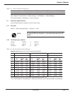
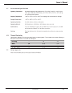
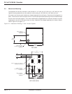
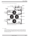
1.4 Mechanical Specifications
Table 1-4: S4 Receiver Cabinet Mechanical Dimensions and Weights
MODEL
7 kVA 14 kVA 21 kVA
HEIGHT (in/cm) 21 / 54 31.5 / 81 42 / 107.9
DEPTH (in/cm) 18.5 / 47.5 18.5 / 47.5 18.5 / 47.5
WIDTH (in/cm) 17 / 43.7 17 / 43.7 17 / 43.7
RECEIVER WEIGHT (lb/kg) 88 / 39.9 111 / 50.3 136 / 61.7
RECEIVER + MODULES 182 / 82.6 299 / 135.6 418 / 189.6
WEIGHT (lb/kg)
RECEIVER SHIPPING 100 / 45.4 123 / 55.8 148 / 67.1
WEIGHT (lb/kg)
Introduction
3.5 to 21 kVA N+1 Inverter
page 1 — 4