


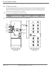


2.13 Start-Up Sequence
Confirm that all power modules’ ON/OFF circuit breakers are set to the OFF position. On the LCD “Display” panel,
be sure inverter switch SW1 is set at STANDBY position.
2.13.1 Power-Up Procedure
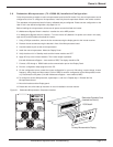
Turn the main source DC input circuit breaker ON to apply 48VC to the system. The “controller” boards and LCD
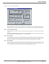
“Display” panels are now energized. The following message will be displayed. See Figure 2-9.
Line 1: INV: off module
Line 2: BYP: static AC LOW
If the system is equipped with two controllers, one controller will take control of the system, the other will be a back-
up. Assuming “Controller A” takes control of the system, the BYPASS Status LED (DS1) will be red, Inverter Status
LED (DS2) will be out, “Controller B” Bypass and Inverter LED's (DS3, DS4) will alternately blink On and Off, green
for Bypass, green for Inverter. If “Controller B” takes control, its Status LED's will be as for “Controller A” above.
If an external AC power source is used, turn on the source AC circuit breaker. After about 20 seconds the LCD
should display the following information:
Line 1: INV: off module
Line 2: BYP: static normal
The “Status” LED's will be as above, except the “Bypass” will be green if the AC input voltage is within proper lim-
its (voltage and frequency).
2.13.2 Powering Up the Inverters
DO NOT turn on the inverter switch SW1 yet! Turn the circuit breaker on each power module to the ON position.
The LCD “Display” panel is still displaying the above two lines, but “module” will change to “normal”. Now, every-
thing is ready and the inverter switch, SW1, can be turned ON (push-up). The “Status” LED's will be as above,
except that the “Inverter” indicator that was out will now be green if the system is functioning properly. The invert-
er is now supplying the power to the system. Using a voltmeter, verify that the proper voltage (110, 115, 120, 208,
220, 230, 240VAC) exist at the output terminals. Load circuit breaker may be turned ON.
2.13.3 De-Energizing the System
If the system is equipped with an AC input, turn off the main feed circuit breaker. Then turn switch SW1 to the stand-
by position (push down). Next, turn all the power modules front panel circuit breakers OFF. Lastly, turn the DC input
supply circuit breaker OFF.
Installation & Operation
3.5 to 21 kVA N+1 Inverter
page 2 — 20