


page 3 — 5
Owner’s Manual
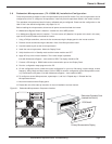
3.8 Redundant Microprocessor (72-153588-00) Installation/Configuration
Follow this procedure to replace or add a microprocessor board to the S4 Inverter. Only one microprocessor can be
configured at a time. To configure a microprocessor, install only that microprocessor board in the inverter receiver.
The redundant microprocessor board is factory calibrated and pre-configured. Please see the configuration on the
label. If this is the desired configuration, skip steps 6 to 10.
Before installing the microprocessor, disconnect all power sources that feed the inverter.
If a Maintenance Bypass Switch is installed – transfer the unit to MBP position.
If no Maintenance Bypass switch is installed – Turn the inverter off (Attention: No power to the load in this case),
open the DC and AC breakers that feed the inverter.
1. Using a Phillips screwdriver, remove the four screws securing the display panel to the inverter receiver.
2. Remove the two screws securing the bracket in front of the Microprocessor board.
3. Use this bracket to pull out the old microprocessor.
4. Install the new microprocessor. Mount the Display Panel.
5. Verify that the unit is in Standby mode and the inverter modules are OFF.
6. Apply AC only to the inverter. Attention: The inverter output is powered.
(Unit with Maintenance Bypass – move switch to SBP) The display should be ON.
7. Connect a PC through a RS232 cable to the communication port on the Display Panel.
8. Run the configuration setup program on the PC.
9. On the configuration screen, select the correct configuration for your unit: KVA rating, inverter voltage, inverter
frequency, Utility, Mode and Auto restart. Click on SAVE to send the configuration to the Microprocessor mem-
ory. Disconnect the AC power. (Unit with Maintenance Bypass – move switch to MBP)
10. To configure a second Microprocessor, repeat steps 1, and 3 to 9. Repeat step 1. Reinstall the first
Microprocessor board.
11. Mount the bracket and the Display panel.
12. Restart the unit; follow start up instruction in the unit installation and user manual.
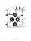
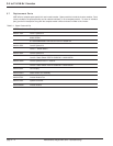
Figure 3-1: Redundant Microprocessor Component Location.
Maintenance Adjustment and Troubleshooting
Primary Microcontroller Display
PCB Slot #2
Redundant Controller Card
(inserted into Slot #1)
Disconnect AC (Mains) and DC supply before removing this cover.WARNING:
DC supply before removing this cover.
Disconnect AC (Mains) and
WARNING:
REMOVING MODULE
!
OPEN BREAKER BEFORE
WARNING!
DC INPUT
GREEN = NORMAL
YELLOW = WARNING
RED = FAULT
STATUS
TEMPERATURE
POWER MODULE
REMOVING MODULE
!
OPEN BREAKER BEFORE
WARNING!
DC INPUT
GREEN = NORMAL
YELLOW = WARNING
RED = FAULT
STATUS
TEMPERATURE
POWER MODULE
!
Disconnect AC (Mains) and DC supply before removing this cover.
CAUTION:
CAPACITOR FUSE
SCROLL
AC RACEWAY
STATUS
STEADY = PRIMARY SOURCE
FLASHING = ALTERNATE SOURCE
BYPASS
STANDBY
COM1
INVERTERBYPASSINVERTER
YELLOW = WARNING
GREEN = NORMAL
RED = FAULT/OPEN
STATUS
A
CONTROLLER
B
CONTROLLER
INVERTER
ON
AC LONEUT
!
Disconnect AC (Mains) and DC supply before removi
ng this cover.
CAUTION:
CAPACITOR
FUSE
SCROLL
AC RACEWAY
STATUS
STEADY = PRIMARY SOURCE
FLASHING = ALTERNATE
SOURCE
BYPASS
STANDBY
COM1
INVERTER
BYPASS
INVERTER
YELLOW = WARNING
GREEN = NORMAL
RED = FAULT/OPEN
STATUS
A
CONTROLLE
R
B
CONTROLLE
R
INVERTER
ON
AC LO
NEUT