


3.9 Troubleshooting and Servicing
Should you encounter a problem in the operation of the inverter and need MGE Systems to service your equipment,
it is recommended to leave the unit in its current state. Record message (if any) and color signals on the LCD dis-
play and LED indicators on the display panel, then call MGE Customer Support Services at 1-800-523-0142 for
assistance. Leaving the unit in its current state will facilitate the field engineers to troubleshoot and bring your equip-
ment back on line more easily. If you cannot wait, you may want to consider the following troubleshooting tips.
3.9.1 Installation Check
Often, operation problems are caused by incorrect installation or setup. Before turning the system on, review
Chapter 2 for instructions pertaining to your particular system. Use the checklist below. If the system fails to oper-
ate properly after being turned on, all items in this list need to be rechecked and verified to make sure things are
connected correctly.
Installation Checklist: (Installed item to be verified)
◗ Inverter System included static transfer switch
◗ DC input terminals have correct voltage polarity
◗ Utility input terminals have correct voltage connections
◗ AC output terminals voltage connections
◗ Input conductor size correct ampacity
◗ Output conductor size correct ampacity
◗ Correct output voltage selected in personalization
◗ Correct frequency selected
◗ On/Off Line Inverter is on-line
◗ Automatic or manual start is selected
3.10 AC Output Circuit Breaker
A Power Distribution Panel is available from MGE UPS SYSTEMS at a nominal cost. Order part number 6421P-9
for 14 or 21 kVA units,
or 6210-0AD for the 7 kVA, which will accommodate up to 20/24 single-pole circuit breakers,
“Square-D” QO type.
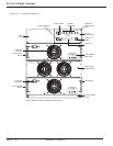
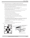
3.10.1 Cable Connection and Static Switch Module
All input and output connection terminals are mounted inside the built-in Static Switch. It is very easy to identify this
module by looking at a front panel that has twin cooling fans. The top panel can be opened with a #2 Phillips screw
driver. When making connection, always double check to make sure that DC cable goes to DC busbars,
identified
as (+) and (-). The utility cables go to a terminal block, for Line to Neutral units 120/240VAC line connects to TB1-2,
NEUTRAL to TB1-4.
AC output is from TB1-1 (120/240VAC), NEUTRAL to TB1-3. For Line to Line units (208-240):
Line 1 connects to TB1-2 and L2 to TB1-4, AC outputs: L1 connects to TB1-1 and L2 to TB1-3. One of the best ways
to verify continuity is to use a DMM.
3.5 to 21 kVA N+1 Inverter
page 3 — 6
Maintenance Adjustment and Troubleshooting