


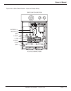


2.10 Redundant Controller Set-Up
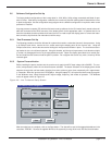
After making sure the 48VDC power has been removed from the unit, remove the two Phillips head screws from the
display panel as above. Re-install the top controller printed board that was previously partially removed. Using the
circuit board retaining bracket, disengage the bottom controller board from its connector. Replace the display panel
and secure it with the two Phillips head screws previously removed. Repeat steps for the second controller. When
the set-up is complete, remove the 48VDC applied to the system. Again open the front display panel and reseat
the bottom controller circuit board. Replace the circuit board retaining bracket and secure it in its final position using
the two 6/32 Phillips head screws. Replace the display panel and secure it to the rack using the two 8/32 x 3/8”
Phillips head screws. Set up is complete.
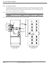
2.10.1 Inverter Module Installation
The power modules are designed to be hot swapped. However, for initial start up, all of the inverter modules should
be installed. In a system where all of the module positions are not used, reinstall the previously removed blank panels
in these locations. Install the inverter modules, and tighten the four thumbscrews on each module. Before turning on
the main source DC circuit breaker and utility AC circuit breaker (if used), make sure that all of the inverter module cir-
cuit breakers (upper left-hand corner) of each module is OFF. Also verify the ON/Stand-by switch on the display panel
is in the Standby (down) position. The inverter plant usually supplies power to some type of distribution circuit break-
er panel. Confirm that all of these circuit breakers (loads) are OFF before starting up the inverter. After the DC input
cable, utility line cable, and output cable are properly connected and secured, the inverter system is ready to be turned
ON.
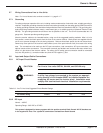
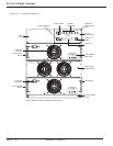
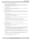
Figure 2-8: Inverter Module.
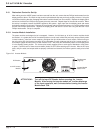
ATTENTION!: Turn off the Input DC Breaker before removing the inverter
Module. After turning the inverter module off, to allow discharge
of the Input capacitors, wait 3 minutes before turning the Inverter
Module back “ON.
Installation & Operation
3.5 to 21 kVA N+1 Inverter
page 2 — 16
REMOVING MODULE
!
OPEN BREAKER BEFORE
WARNING!
DC INPUT
GREEN = NORMAL
YELLOW = WARNING
RED = FAULT
STATUS
TEMPERATURE
POWER MODULE
Inverter Module
Status LEDs
DC Breaker
3.5 kVA Inverter
Module
Thumbscrews
(4 typical)