


The utility input and output cables are connected to a screw type terminal block. Connect the ground wires first,
then the neutral wires, then connect the AC input wire (if applicable) and the AC output wire. A separate, optional
Maintenance Bypass unit and a Power Distribution panel (200A Square D “QO” type of circuit breakers) are avail-
able.
2.5.5 AC Input/Output Voltage Selection
The inverter is preset at the factory for 120VAC input, ON-LINE, 120VAC, 60 Hz output.
If the input voltage for your installation is different (220VAC to 240VAC), the following procedure MUST be followed.
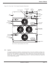
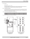
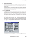
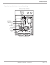
In the static switch area, there is a printed circuit board mounted to the right side panel. A multi-pin connector is
located on the printed circuit board, close to the static switch front panel, identified as J23. This connector has 13
pins. Its mating plug has 12 positions, with interconnecting wires. This allows the jumper plug (P13) to be installed
in one of two positions. When this jumper plug is in it most forward position (closest to the front panel), the unit is
set for 110-120VAC operation. Removing the plug and installing it in its rear most position selects 220-240VAC
operation. Verify that this plug is in the proper position before applying any voltage to the inverter system. See
Figure 2-4.
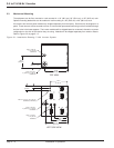
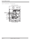
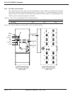
2.5.6 EMI Filter Wiring
There are two separate inverter AC output EMI filters. Each filter provides one half of the output power to the sys-
tem. These filters must be connected in parallel for 110-120VAC output or connected in series for 220-240VAC out-
put. There are only two wires connected to these two filters. The neutral wire, with the white band, is connected to
the lower EMI filter left-hand stud. The AC output wire is connected to the upper EMI filter right-hand stud. In the
110-120VAC configuration, the left-hand studs of the EMI filters are connected together by a copper busbar strap
and the two right-hand studs of the EMI filters are connected together by a busbar strap. See Figure 2-4.
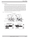
To change to the 220-240VAC connection, remove the wires and busbars from the output terminals of the EMI fil-
ter. Install the copper busbar between the lower EMI filter right-hand stud to the upper EMI filter left-hand stud. Re-
connect the white neutral wire to the lower EMI filter left-hand stud and the AC output wire to the upper EMI filter
right-hand stud. Replace the hardware (flat washer, lock washer, and nut) and tighten the 10MM nuts to the pre-
scribed torque, 35.4 inch-lbs (4 Nm). Refer to the decal on the cover plate of the static switch for strap positions.
Again, verify that P23 plug on the static switch printed circuit board (located on the right side panel, is in the 240VAC,
rear most position before applying any voltage to the inverter system. The extra copper busbar may be discarded.
Replace the top cover of the static switch and secure it with the three previously removed 6-32x1/4” Phillips head
screws.
WARNING: Do not perform this procedure (under Section 2.5.6) unless
the configuration needs to be changed. The voltage selection
jumper plug position must agree with the software selection.
See Figure 2-4 EMI filter strapping.
Installation & Operation - Line To Neutral
3.5 to 21 kVA N+1 Inverter
page 2 — 8