


page 3 — 3
Owner’s Manual
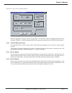
3.3 Equipment Adjustment and Calibration
The equipment is factory adjusted and, normally, no further adjustments and calibration are required. However, in
the course of repair, components may have to be changed that will require configuration of the equipment. These
configurations should only be made by a qualified technician.
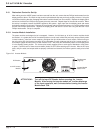
3.4 Air Intake Cleaning
Inspect the air intake and exhaust openings for blockage. Verify that air flows freely through the equipment. Clean
the air intake and exhaust openings with a vacuum and a soft brush.
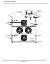
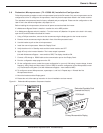
3.5 AC Fan Replacement
Every five years, replace the Static Switch front panel, including fans (MGE part number 64004-0SSK1). This is
accomplish by removing all the DC and AC power to the unit by turning the Maintenance Bypass Switch to the MBP
position.
Perform the following steps:
1. Remove the front panel from the “static switch panel (with two fans), using a #2 Phillips screw driver take out the
four screws securing the panel to the receiver rack.
2. Unplug the two fan wires at the static switch printed circuit board.
3. Install the fan assembly onto the static switch, making sure to plug fan’s back into the static switch printed cir-
cuit board connectors.
4. Secure the front panel in place by using the four Phillips”head screws previously removed.
5. Power up the system by switching the Maintenance Bypass Switch to SBP and to Normal.
6. Close DC Breaker and verify that the inverter is in normal mode - display panel inverter indicator should be
green.
7. Verify that the Inverter output indicator on the Maintenance Bypass Switch display is “ON”.
3.6 DC Fan Replacement
Every five years, replace the DC fan in each power modules (MGE fan part number 64004-0FSK1). This is accom-
plished by removing the power module from the receiver.
Perform the following steps:
1. Remove the front panel from the power module by removing the six Phillips head screws securing the front panel
to the chassis, the two screws securing the top cover to the front panel (6-32” Phillips head screws), and the two
screws hold the DC circuit breaker to the front panel. It should not be necessary to remove the top cover.
2. Remove the front panel, being careful to unplug the fan from the printed circuit board.
3. Observe the orientation of the fan wires and the fan guard so that it will appear like all other power module front
panels. Remove the fan from the front panel by removing the four screws holding the fan, panel, and fan guard
together.
4. Install the new fan in the reverse order of disassembly. When installing the front panel onto the chassis, care
must be taken to ensure the three LED’s project through the front panel. Install all ten flat head screws.
5. Make sure the circuit breaker on the front panel is in its OFF position.
6. Install the inverter module back into the receiver rack.
Maintenance Adjustment and Troubleshooting