


Installation & Operation
page 2 — 3
Owner’s Manual
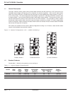
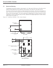
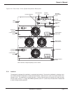
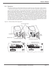
Figure 2-2: Front View, 7 kVA, System Component Description.
2.3.1 Location
The equipment is designed for installation in a protected environment. Factors to be considered in selecting a loca-
tion include ventilation, temperature, humidity, and accessibility. Install the unit in a clean, dry location with an unre-
stricted air flow. The equipment is cooled by forced air. Allow at least 6 inches of air space to the sides of equip-
ment for proper cooling. To comply with NEBS requirement, allow 12” (30.48 cm) to the sides when installed next
to other heat generating equipment.
Disconnect AC (Mains) and DC supply before removing this cover.
WARNING:
DC supply before removing this cover.
Disconnect AC (Mains) and
WARNING:
REMOVING MODULE
!
OPEN BREAKER BEFORE
WARNING!
DC INPUT
GREEN = NORMAL
YELLOW = WARNING
RED = FAULT
STATUS
TEMPERATURE
POWER MODULE
REMOVING MODULE
!
OPEN BREAKER BEFORE
WARNING!
DC INPUT
GREEN = NORMAL
YELLOW = WARNING
RED = FAULT
STATUS
TEMPERATURE
POWER MODULE
Inverter on/Stand by
Communications
Port
Controller
Status LEDs
Primary
Microcontroller
LCD Scroll
Button
LCD Panel
Inverter Module
Status LEDs
Static Transfer
Switch Cabinet
Thumb Screw
Receiver Cabinet
Chasis
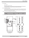
NOTE: Modules are shipped separately to receiver cabinet.
Alarm
Panel
Inverter DC
Input Switch
Cooling Fan
Assembly
3.5 kVA Inverter
Module
Redundant
Microcontroller
Panel
3.5 kVA Inverter
Module
!
Disconnect AC (Mains) and DC supply before removing this cover.
CAUTION:
CAPACITOR FUSE
SCROLL
AC RACEWAY
STATUS
STEADY = PRIMARY SOURCE
FLASHING = ALTERNATE SOURCE
BYPASS
STANDBY
COM1
INVERTERBYPASSINVERTER
YELLOW = WARNING
GREEN = NORMAL
RED = FAULT/OPEN
STATUS
A
CONTROLLER
B
CONTROLLER
INVERTER
ON
AC LONEUT