


Installation & Operation
page 2 — 17
Owner’s Manual
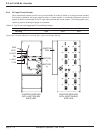
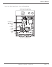
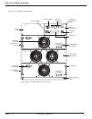
2.11 Indicators and Controls
There are six LED indicators divided into three groups – DS1 and DS2, DS3 and DS4, DS5 and DS6 - on the dis-
play front panel. DS1 and DS2 are indicators of controller A; DS3 and DS4 are indicators for controller B; DS5 and
DS6 are for output capacitors fuse indicators. Failure of output capacitors will trip output fuses, and will activate
DS5 and/or DS6 indicators. See Figure 2-9.
At power-up, one of the two controller units will be up quicker than the other and will take control the system. The
stand by controller LED’s will be green, toggling on/off. Consequently DS1 or DS3 will be on blinking green, sig-
naling that AC Input is available and the system output is ready to be turned on, through the Power Distribution
breakers.
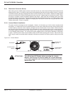
The inverter output voltage is turned ON or to Stand-by via switch SW1 located on the left side of the LCD display
panel. Pushing it up is to turn the inverter ON, and pushing it down is to turn the inverter OFF. WARNING: In the
stand-by position, if AC power is applied to the AC input terminal block, AC power will be on the output of the unit.
When the Inverter voltage is on, DS2 (or DS4) indicator will be on green steadily, signaling that every thing is nor-
mal.
The system measurement information is displayed on the LCD display panel. Switch SW3 (scroll button, on the right
side of the display panel), is pushed down (or up) to scroll the LCD’s screens for more information. Individual invert-
er module has only one control, an ON/OFF circuit breaker, located at the upper left corner of the front panel. This
breaker is used to energize (or de-energize) the inverter module.
Note: For initial start-up the module circuit breakers must be turned on prior to turning the system Inverter “ON”.
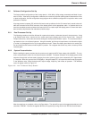
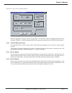
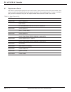
2.11.1 LCD Readout
The LCD unit displays two lines (out of a total of seven lines) of information at a time. Each line can be scrolled
up (or down) independently by toggling the scroll switch SW3. Typical seven lines of information are shown below:
Line 1 INV: off normal Inverter off/on
Line 2 BYP: static normal Static bypass on/normal operation
Line 3 LOAD: 120V 100% AC Output/Load % of nominal
Line 4 AC IN: 120V 60 Hz AC input voltage/frequency
Line 5 DC IN: 48.0V 073.5A DC voltage/DC current
Line 6 LOAD: 03000 W 025.0A Load Power (W)/Current (A)
Line 7 INV: 6 of 6 60 Hz Number of good modules out of #
installed modules
Operation/Frequency.