


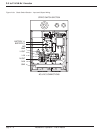

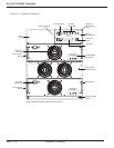

2.8.4 Connections
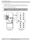
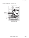
All DC input connections are made through the knock-outs, located in the top or left side panel. Refer to Figure 2-
1. Make sure that the upstream source DC circuit breaker and AC circuit breaker (if applicable) supplying the invert-
er are in the off (or open) position. DC input power cables should be sized such that the maximum voltage drop
between inverter busbar terminals and battery terminals is less than 1.0 volt at the breaker current rating. See Table
2-4 for CB breaker rating verses kVA rating. The inverter can accommodate three positive wires and three nega-
tive wires up to 4/0. Two 3/8” hole lugs, compression type with hole spacing of 1” should be used. All ground con-
nections should be made first, then positive (+) DC input cable should be connected, then the negative (-) connec-
tion last. The DC input landings are marked (+) and (–). Insert the input DC power cable through the selected top
or side panel knock-out. Connect the positive (+) cable to the lower terminal connection and the negative (–) cable
to the upper terminal connection landing. The 14 kVA and 21 kVA inverter require the super flexible (fine strand)
wire, which is installed with an optional Maintenance Bypass unit, and with an optional Junction Box that is mount-
ed to the back side of the Inverter receiver (14kVA and 21 kVA only). See Figure 2-6.
The utility input and output cables are connected to a screw type terminal block. Connect the ground wires first,
then connect the AC input wires (if applicable) and the AC output wires. A separate, optional Maintenance Bypass
unit and a Power Distribution panel (125/200A Square D “QO” type of circuit breakers) is available.
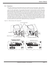
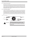
2.8.5 AC Input/Output Voltage Selection
The inverter is preset at the factory for 240VAC input, ON-LINE, 240VAC, 60 Hz output. If the input voltage for your
installation is different (208VAC to 240VAC), the following procedure MUST be followed.
2.9 Software Configuration Set-Up
The factory default configurations of the inverter plant is: 240V, 60Hz, Utility voltage connected and Mode of oper-
ation is Online. If the factory configuration is different the inverter plant will ship with marking that will describe the
inverter plant configuration. Use the configuration setup program when a different configuration is required or when
a new processor is installed.
A lap-top personal computer (PC) with the field service set-up software for the S4 inverter family needs to be avail-
able and connected to the DB-9 connector of the display panel via the appropriate cable. In systems that do not
have the redundant controller printed circuit board, there is no need to open the display panel or remove the redun-
dant controller, skip the dual and redundant controller setup.
2.9.1 Dual Processor Set-Up
The following procedure should be followed for systems that contain a redundant (second) microprocessor. Using
a #2 Phillips screw driver, remove the four screws securing the display panel to the receiver rack. Using the
Phillips”screw driver, remove the two screws holding the microprocessor boards in place. The circuit board secur-
ing bracket is also a circuit board extractor. Using this bracket, pull the top microprocessor circuit board out slight-
ly so that it is disengaged from its 70 pin edge plated connector. Return the display panel back to its vertical posi-
tion and install the two screws to hold the panel in position. Do not tighten the screws very much, since they will be
removed again.
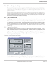
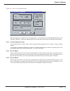
2.9.2 System Personalization
Before installing the power modules into the receiver rack, apply the 48 VDC input voltage (44 to 56VDC). The
controller (microprocessor) within the unit should become activated. The status indicators on the display” panel
should sequence through their self test mode, changing from red to yellow to green, then momentarily off in approx-
imately 4 seconds. After this, ignore all the LED displays. Using the laptop PC, call up the filed service set-up pro-
gram. In the Windows menu, select the desired inverter voltage, frequency, and modes of operation. The Windows
menu will appear similar to Figure 2-7.
Installation & Operation - Line To Line
3.5 to 21 kVA N+1 Inverter
page 2 — 14