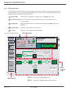
GCC Setup
page 2 — 3
User Manual
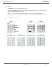
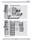
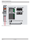
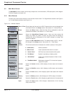
Figure 2-2: S-M Identification Setup Screen.
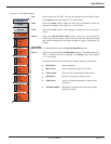
Figure 2-3: M-M Identification Setup Screen.
Opens the System Configuration Screen.
Alarm
Popup
Screen
Set to have Alarm Screen automatically
open when new Alarm/Event happens
Change
Password
UPS 1
Load
Protected
ALARMS
07:34:18
01/24/2003
Setup
Control
Panel
Select if UPS is a 225, 300, 375 or 500KVA
Battery Temp.
Sensor present
Show battery
Backup time
Q3BP
Q5N
Q4S
Show CB's
Identification Setup
9 character max
UPS Name
Rectifier Input CB
Bypass Input Breaker
UPS Output Breaker
System Bypass Breaker
Battery Breaker
Input 1
Input 2
UPS 1
Q1
Q4S
Q5N
Q3BP
QF1
Utility 1
Utility 2
7
3
4
1
8
5
6
2
Change
Password
UPS 1
Load
Protected
ALARMS
07:34:18
01/24/2003
Setup
Control
Panel
Identification Setup
9 character max
System Name
UPS 1 Name
UPS 2 Name
UPS 3 Name
UPS 4 Name
UPS 5 Name
UPS 6 Name
UPS 1 Input CB
UPS 2 Input CB
UPS 3 Input CB
UPS 4 Input CB
UPS 5 Input CB
UPS 6 Input CB
UPS 1 Output CB
UPS 2 Output CB
UPS 3 Output CB
UPS 4 Output CB
UPS 5 Output CB
UPS 6 Output CB
System
Config.
Battery Breaker UPS 1
Battery Breaker UPS 2
Battery Breaker UPS 3
Battery Breaker UPS 4
Battery Breaker UPS 5
Battery Breaker UPS 6
Static Switch Input Brteaker
Static Switch
System Output Breaker
Maint. Bypass Breaker
Input 1 (UPS Input)
Input 2 (Bypass)
System
UPS 1
UPS 2
UPS 3
UPS 4
UPS 5
UPS 6
Q1
Q1
Q1
Q1
Q1
Q1
Q5N
Q5N
Q5N
Q5N
Q5N
Q5N
QF1
QF1
QF1
QF1
QF1
QF1
Q4S
Q2S
Q5N
Q3BP
Main 1
Bypass
1
8
7


