User Manual
GCC Troubleshooting
GCC Troubleshooting
page 6 —1
6.0 Scope
This section contains a troubleshooting guide to assist the User with any communication and configuration
problems.
6.1 Communication and Configuration
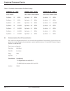
The GCC is factory tested and ready to use upon receipt. Proper hardware connections, personalization and Dip
switch settings are necessary for operation.
The following sections may provide assistance for any communications fault and GCC start-up issues. If support is
required, contact MGE Customer Support Services at 1-800-438-7373.
◗ RS485 Interface Connections.
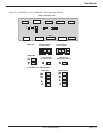
◗ Communications Port Switch Settings.
◗ Communications Port 2 Personalization.
◗ GCC Port Connections.
◗ RS232/RS485 Interface Converter.
◗ Auto Start.
◗ Rebooting.
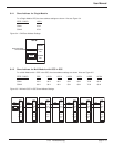
◗ GCC Identification Label.
6.2 RS485 Interface Connections
The RS485 connects multiple items that have unique addresses on a common bus. Each item is referred to as a Cubicle
(or slave). MGE's addressing method increments each cubicle in 10’s hexadecimal.
Depending upon your GCC configuration, the RS485 interface connections are either connected as a Single-Module
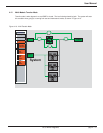
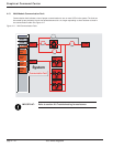
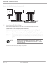
or Multi-Module. The diagrams below show how the cables are connected; Figure 6-1 is for a Single-Module, Figure
6-2 is for a Multi-Module.
6.2.1 Twisted Pair Connection Using Terminal Blocks
To function properly, the RS232/RS485 converter needs two twisted pairs of metallic wire. These pairs must be
between 19 and 26 AWG (the higher number gauges may limit distance).
Figure 6-1: S-M RS485 Interface Connections with GCC.
UPS 1
GCC
RS232/RS485
CONVERTER
12345678910
12345678910
RAUZ1 PCBA / GTCZ COM2
T-
R-
T+
R+
XR11
4 COND. SHIELDED CABLE OR DUAL TWISTED PAIR WIRE
No Connection


