


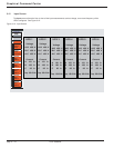
4.0 Scope
This section provides GCC mimic diagrams representing the common status and fault modes.
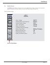
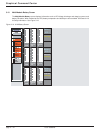
4.1 Color Status Indicators
A color standard has been established to indicate the status of the UPS or SSC operation as follows:
Green = Normal / Power Flow.
Yellow = On Battery, (for Multi-Module only).
Red = Major Alarms / Fault.
Blue = Test Mode / Power Flow.
Grey = OFF & No Faults.
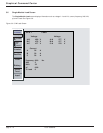
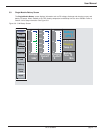
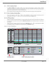
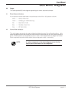
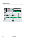
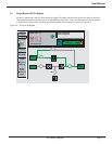
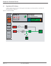
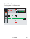
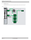
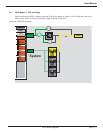
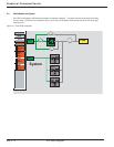
4.2 Power Flow Indicators
The mimic diagram representing the system configuration displays the power flow and breaker positions. Active
power flow paths are shown with colored lines, and non-active or broken paths use gray lines (except input will be
green). Breaker positions are recognizable as open or closed. Active components on the diagram are labeled.
Active components include the inverter, rectifier, load, and input (such as Utility 1 and Utility 2).
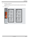
NOTE: An active component on the mimic diagram causes the dis-
play to open to the screen for that component.
Users Manual
GCC Mimic Diagrams
GCC Mimic Diagrams
page 4 —1