


PH50, XL50, XL21 series Set-up and Installation Manual
70
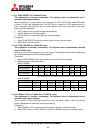
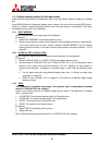
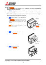
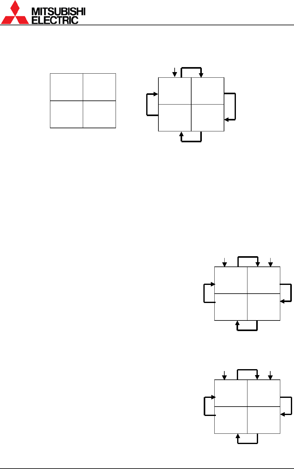
H=1/2
V=1/2
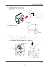
H=2/2
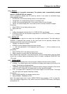
V=1/2
H=2/2
V=2/2
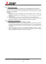
H=1/2
V=2/2
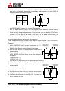
4. Set the position and expansion ratio (“
1.8.2 H.DISPLAY POS, V.DISPLAY POS” on page66)
again to fit a configuration in reference to the following setting sample in left side. Check the
displaying to be as the example in right side.
5. Set SCREEN MODE (chapter
1.8.6, on page 67) as needed.
6. Save the display memory (chapter 1.8.7, on page 68) of each screen in a different memory
number from a previous saving.
7. Check the image linkage between screens. If it is insufficient, you can tweak by OFFSET menu
(chapter
1.5.1.7, on page 38). Be careful if you adjust it by the display memory setting, the
linkage condition may change when you display other images.
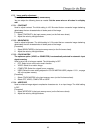
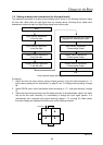
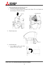
You can also display different input images in the same time.
It is an example that an analog signal A is input to panel 1 (upper left) and a video (COMPOSITE)
signal V is input to panel 2 (upper right). Each screen is connected with daisy chain.
[Procedure]
8. Select COMPOSITE port in the panel 2 according to “
1.7.1
Input port selecting” on page 57.
9. Adjust the input memory setting in the panel 2 as needed.
10. Save the input memory in a different memory number from a
previous saving.
11. Set the display memory in the panel 2 as below.
INPUT MEMORY: the input memory for the video input set in
the step 10.
H.DISPLAY POS.: 1/1
V.DISPLAY POS.: 1/1
DIGITAL OUT: the input memory for the digital input set in the step 3.
12. Make certain to display the video signal V on the panel 2 as described above.
13. Save the display memory in a different memory number from a
previous saving.
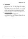
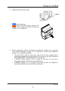
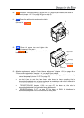
You can switch these image displays.
[Procedure]
14.
Regarding the panel 2 as a first cube, follow the same procedure
as step 2 to 7 to display as shown in the right figure.
15. Call display memories (set in the step 3, 6 13 or 15) to switch the
display depending on cases.
A
Image signal
A
V
Image signal 1
(Analog input)
Image signal 2
(Video input)
V
Image signal 1
(Analog input)
Image signal 2
(Video input)