


PH50, XL50, XL21 series Set-up and Installation Manual
24
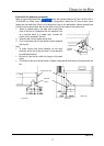
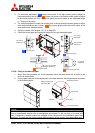
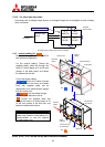
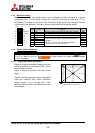
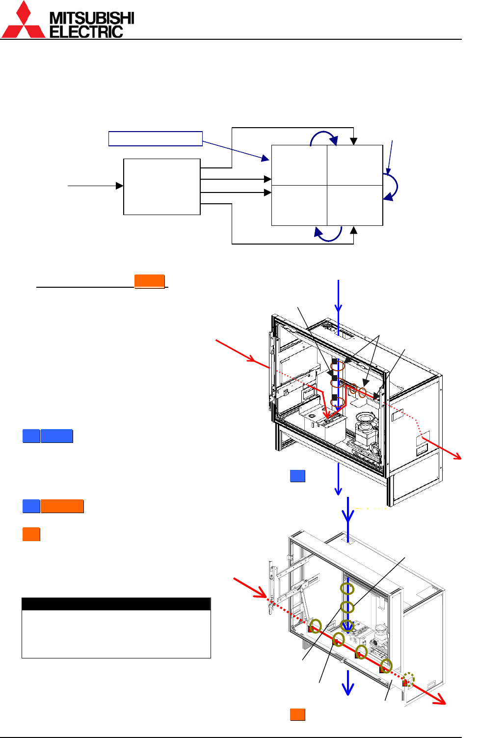
1.3.2.2. For other than daisy chain
Connecting with a multiple-output device, an enlarged image can be displayed as well as daisy
chain connection.
Connecting with a multiple-output device (example)
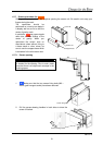
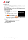
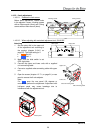
1.3.3. Internal cabling (for
F
F
r
r
o
o
n
n
t
t
)
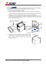
Run cables through the holes located on
both sides and top/bottom.
For the vertical cabling: Thread the
supplied plastic cable ties through the
holes in 3 mount bases to fix on the rear
surface of the back panel, and fasten
the cables with the ties.
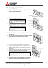
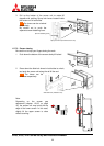
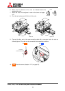
For the horizontal cabling:
5
5
0
0
”
”
S
S
i
i
n
n
g
g
l
l
e
e: Route the cables through
the guide below the mirror and fasten
them with supplied cable ties as
appropriate not to shade picture images
from the optical unit.
5
5
0
0
”
”
C
C
h
h
a
a
n
n
g
g
e
e
r
r: Run the cables through
the cable guide behind the mirror.
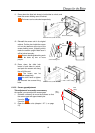
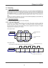
6
6
7
7
”
”: Thread the supplied cable ties
through the holes in 5 mount bases to fix
on the rear surface of the skirt part, and
fasten the cables with the ties.
Caution
For the safety reason, do not allocate a
power strip inside the cube cabinet. It is
recommended to use the optional
3-meter power cord.
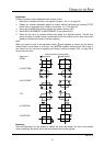
ID 1
MASTER
ID 2
SLAVE
ID 4
SLAVE
ID 3
SLAVE
Multiple-output
device
Input image
External controller
Supplied
control cables
Horizontal
cabling
Vertical
cabling
Plastic cable ties
Mount bases
Cable guide
Horizontal
cabling
Vertical cabling
Mount bases
(for vertical)
Mount bases
(for horizontal)
Plastic
cable ties
For
5
5
0
0
”
”
For
6
6
7
7
”
”
Skirt part