


PH50, XL50, XL21 series Set-up and Installation Manual
62
1.7.4.11. SYNC SELECT (for S.ANALOG input)
This adjustment is normally unnecessary. The optimum value is automatically set in
automatic input signal scanning.
Used to select sync on green setting. The initial setting is AUTO. HD/VD may make FINE easier
to match in 5-line input (separate sync). Set SOG (sync on green) for 5-line (separate sync) or
4-line (composite sync) input with sync on green signals since this clamp pulse on the green
channel cannot be adjusted.
• AUTO: Select to set the optimum signal automatically.
• HD/VD: Select for a 5-line input signal.
• SOG: Select for an input signal with sync on green signals.
[Procedure]
1. Select SYNC SELECT in the input memory menu (on the 4th menu sheet).
2. Select AUTO, HD/VD or SOG.
1.7.4.12. CLOCK RANGE (for S.ANALOG input)
This adjustment is normally unnecessary. The optimum value is automatically selected
when H.TOTAL is set.
Used to set the dot clock frequency of an input signal. The displayed values and corresponding
dot clock frequencies are shown in fallowing tables.
[Procedure]
1. Select CLOCK RANGE in the input memory menu (on the 4th menu sheet).
2. Adjust the value by left/right buttons.
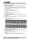
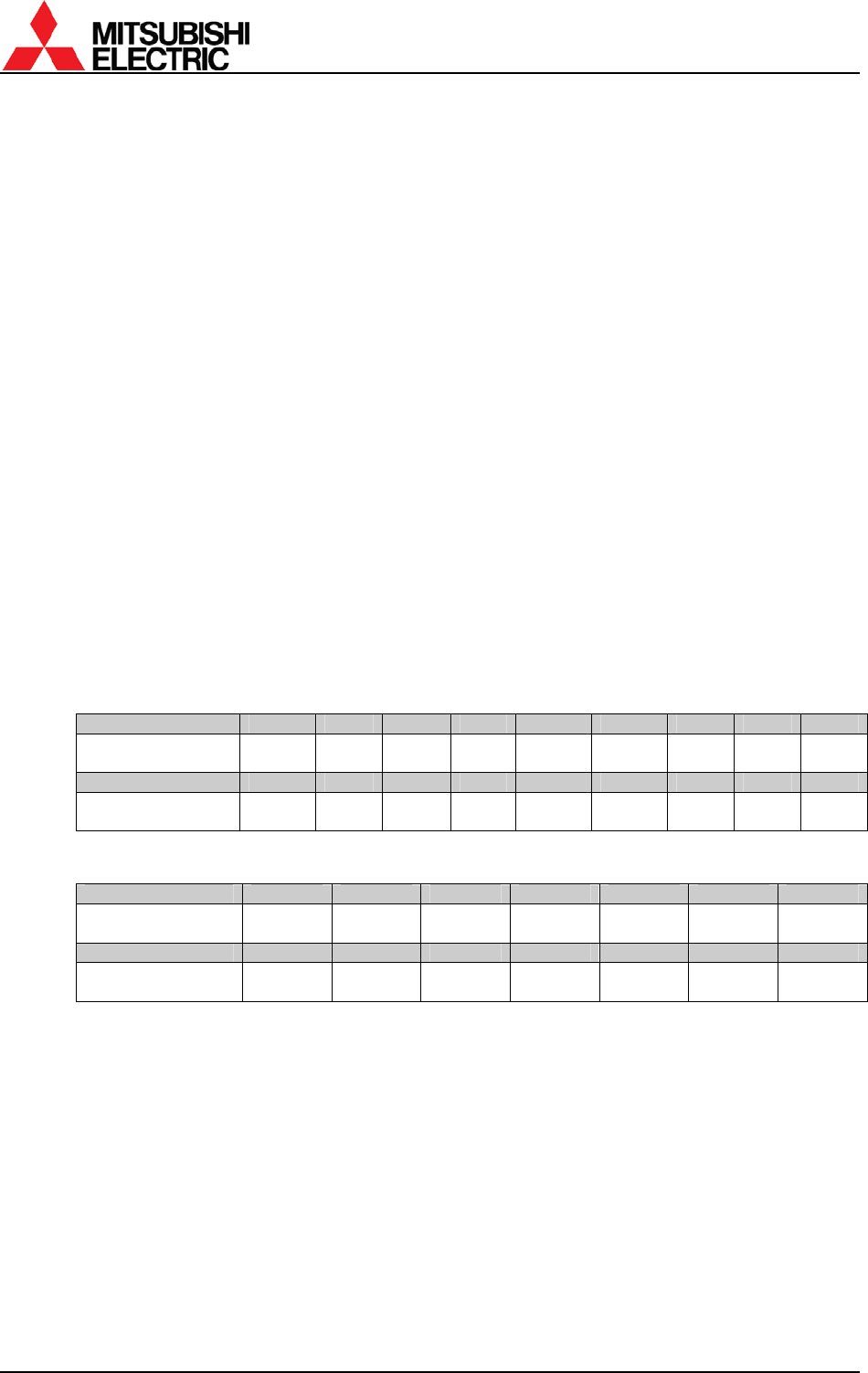
With VC-B50KA
CLOCK RANGE 1 2 3 4 5 6 7 8 9
Dot clock [MHz] – 20
20 –
28
28 –
38
38 –
45
* *
45 –
61
61 –
77
77 –
82
CLOCK RANGE 10 11 12 13 14 15 16 17 18
Dot clock [MHz] * *
82 –
122
122 –
146
* * 146 – * *
*) Dot clock frequency is maintained even if the clock range number changes.
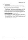
With VC-B20KA
CLOCK RANGE 5 6 7 8 9 10 11
Dot clock [MHz]
21.25 –
27.5
27.5 – 35
35 –
38.75
38.75 –
40
40 – 42.5 42.5 – 55 55 – 70
CLOCK RANGE 12 13 14 15 16 17 18
Dot clock [MHz] 70 – 77.5 77.5 – 80 80 – 85 85 – 110 110 – 140
140 –
155
155 –
165
1.7.4.13. SIGNAL TYPE (for S.ANALOG or S.DIGITAL input)
This adjustment is normally unnecessary. The optimum value is automatically set in
automatic input signal scanning.
Used to switch an input signal type according to an input signal. Adjust it when an incorrect
image is displayed after automatic input signal scanning.
[Procedure]
1. Select SIGNAL TYPE in the input memory menu (on the 4th or 2nd menu sheet).
2. Select RGB, YPbPr or YCbCr (RGB or YUV with VC-B20KA) according to the input signal.