


REV 2.4
5
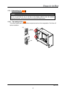
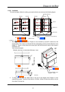
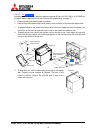
1. Set-up and installation
1.1. Overview
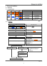
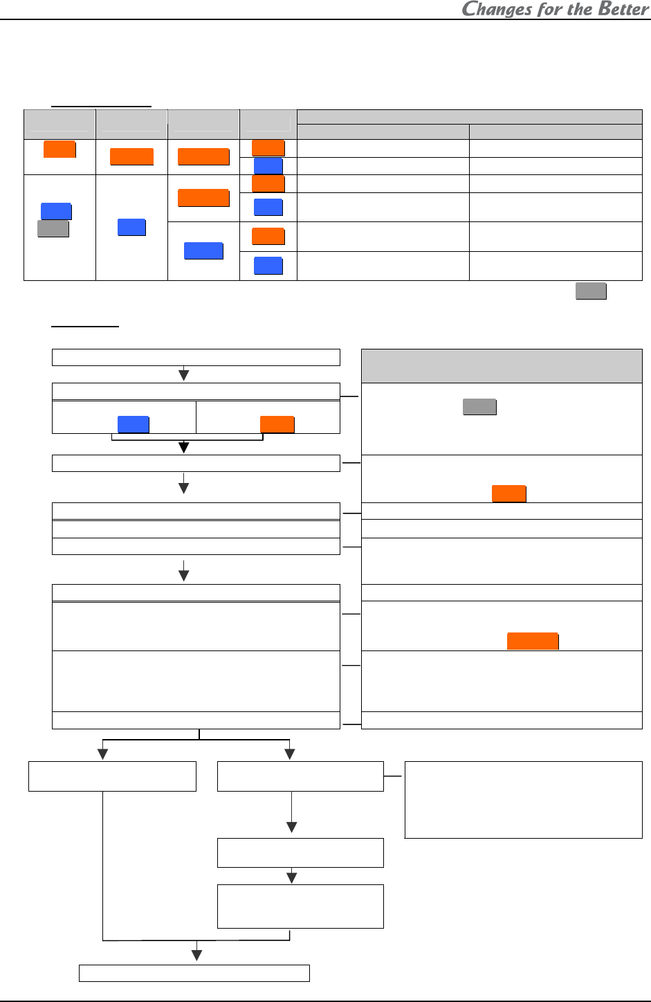
1.1.1. Product lineup
Screen size
Lineup Resolution Lamp Access
50” 67”
F
F
r
r
o
o
n
n
t
t
– VS-67PHF50U
P
P
H
H
5
5
0
0
series
S
S
X
X
G
G
A
A
+
+
C
C
h
h
a
a
n
n
g
g
e
e
r
r
R
R
e
e
a
a
r
r
VS-50PH50U VS-67PH50U
F
F
r
r
o
o
n
n
t
t
VS-50XLWF50U VS-67XLWF50U
C
C
h
h
a
a
n
n
g
g
e
e
r
r
R
R
e
e
a
a
r
r
VS-50XLW50U
(VS-50XLW20U)
VS-67XLW50U
(VS-67XLW20U)
F
F
r
r
o
o
n
n
t
t
VS-50XLF50U
(VS-50XLF20U)
VS-67XLF50U
X
X
L
L
5
5
0
0 /
(
X
X
L
L
2
2
1
1)
(*1)
series
X
X
G
G
A
A
S
S
i
i
n
n
g
g
l
l
e
e
R
R
e
e
a
a
r
r
VS-50XL50U
(VS-50XL21U, VS-50XL20U)
VS-67XL50U
(VS-67XL21U, VS-67XL20U)
(*1) Parenthesized products are
X
X
L
L
2
2
1
1 series.
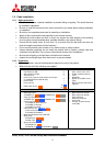
1.1.2. Flowchart
Start
Major setting items
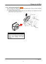
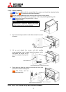
1.2 Cube installation
1.2.5 Cube stacking
(for
R
R
e
e
a
a
r
r
)
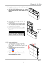
1.2.6 Cube stacking
(for
F
F
r
r
o
o
n
n
t
t
)
•
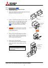
Input board installation (optional)
• Unlocking (for
X
X
L
L
2
2
1
1
)
1.3 Connecting
• Control signal connection
•
Image signal connection
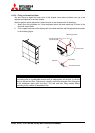
• Internal cabling (for
F
F
r
r
o
o
n
n
t
t
)
1.4 Initial set up
•
Operation mode (to advanced mode)
1.4.2 Dipswitch setting
1.4.3 Picture outline adjustment
•
Displaying internal test pattern
• 6-axis adjustment
• Mirror adjustment
1.5 System memory setting
1.5.1 System set up
•
LAMP POWER
•
SYSTEM SYNC
• HOT EXCHANGE (for
C
C
h
h
a
a
n
n
g
g
e
e
r
r)
1.5.2 Color balance adjustment
•
CSC
•
GRADATION
• TARGET COLOR
•
SENSOR
1.5.3 Image set up
(When necessary)
1.6 Input memory setting
(for the main input)
1.7 Input memory setting
(for the input board)
• Input port selecting
•
Automatic input signal scanning
• H.POSITION, V.POSITION
• FINE
• AMP GAIN
1.8 Display memory setting
(for the input board)
1.9 Setting as daisy chain
connection (for the input
board)
Finish