


REV 2.4
11
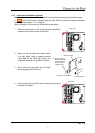
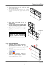
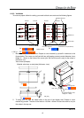
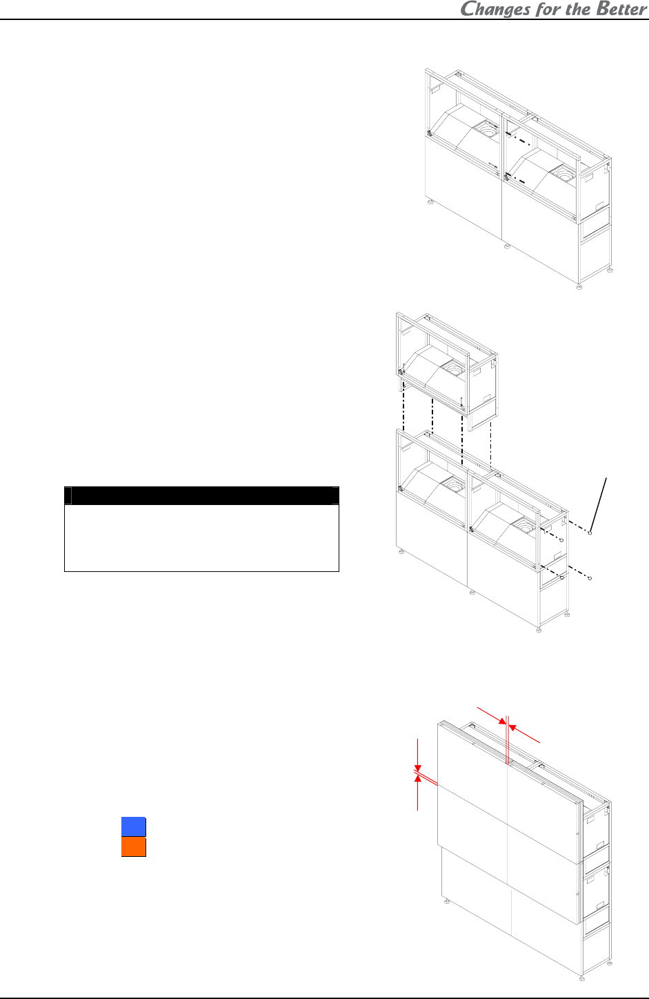
8. Place the next bottom row cube on the base stand
and fix it in the same way.
9. Join right and left cubes at 4 points with supplied
hexagon socket head bolts, spring washers and flat
washers.
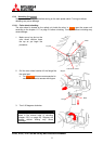
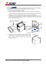
10. Place cubes for the upper row on the
assembled units.
11. Fix them vertically and horizontally at 4 points
each with supplied hexagon socket head bolts,
spring washers and flat washers.
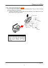
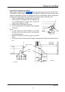
12. Stop up the holes on both sides with supplied
joint hole seals, which holes are not used for a
display wall.
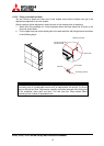
Caution
To avoid units from falling, measure
horizontal and vertical degrees with a
level etc. to make sure the units are
stably assembled.
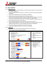
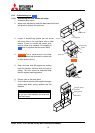
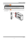
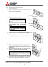
1.2.5.2. Screen gap adjustment
1. Temporarily attach the screen units, which
were detached in the previous step. (For
67-inch models, the screens were supplied
separately).
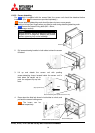
2. Put spacers between screens and adjust the
screen gaps to be:
1 mm for
5
5
0
0
”
” or
2 mm for
6
6
7
7
”
”.
3. Tighten the 4 screen-fixing screws. Be
careful not to tighten with an excessive
torque (suggested torque: 3.9Nm).
1mm
(2mm)
1mm
(2mm)
Joint hole seals