


201
APPENDICES
A
Appendix 1 Buffer Memory Details
Appendix 1.1 Module operation area
Appendix 1.1 Module operation area
The operating status of the Ethernet adapter module is stored.
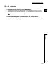
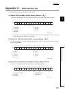
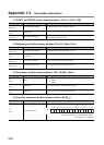
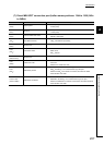
(1) Module LED information (buffer memory address: 0 (0
H
))
Information on the LED status of the CC-Link IE Field Network part is stored in the following bit pattern.
*1 These LEDs can be used only when the Ethernet adapter module is in the online mode. The LED display is not changed
while the Ethernet adapter module is in the offline mode.
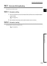
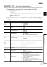
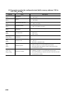
(2) Station No. LED information (buffer memory address: 1 (1
H
))
The status information on the LEDs indicating the station number on the CC-Link IE Field Network part is stored
in the following bit pattern.
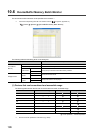
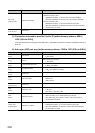
(3) Ethernet port LED information (buffer memory address: 2 (2
H
))
Information on the LEDs of the Ethernet part is stored in the following bit pattern.
1) D LINK LED 2)
RD LED
*1
3) L ERR. LED 4) RUN LED
5) MODE LED 6)
SD LED
*1
7) ERR.LED
0: Off, 1: On
1) 1 for x1 2) 2 for x1
3) 4 for x1 4) 8 for x1
5) 1 for x10 6) 2 for x10
7) 4 for x10 8) 8 for x10
9) 1 for x100
0: Off, 1: On
1) LINK/SPEED 100Mbps 2) LINK/SPEED 1Gbps
3) INT LED 4) COM.ERR. LED
5) SD/RD LED
0: Off, 1: On
0(0H)
b0b1b2b3b4b5b6b7b8b9b10b11b12b13b14b15
1)2)3)4)6) 5)7)
0000 0000 0
1(1H)
b0b1b2b3b4b5b6b7b8b9b10b11b12b13b14b15
1)2)3)4)5)6)7)8)9)
0000000
3(3H)
b0b1b2b3b4b5b6b7b8b9b10b11b12b13b14b15
1)2)3)4)5)
000000 0 0 000