


59
CHAPTER 6 INSTALLATION AND WIRING
6
6.4 Wiring
6.4.1 Wiring of the power supply part
6.4 Wiring
6.4.1 Wiring of the power supply part
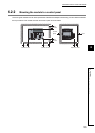
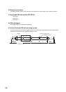
(1) Wiring method
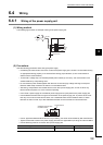
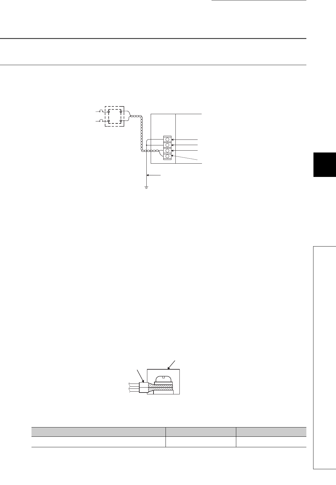
The following figure shows an example of wiring to the power supply part.
(2) Precautions
Take the following precautions when wiring the power supply.
• Considering the rated current and inrush current of the power supply part, connect a circuit breaker having
an appropriate sensing property or an external fuse causing proper blowout. (A 10A circuit breaker or
external fuse is recommended.)
• To minimize a voltage drop, use thickest possible power cables (up to 2mm
2
), and connect them in the
shortest distance by finely twisting them.
• Do not install the power cables together with the main circuit lines (high voltage and large current) and
Ethernet cables. Keep a distance of 100mm or more between them.
• After wiring, always attach the included terminal cover to the power supply part, and do not touch any
terminal while the power is on or the module is operating.
• Use a Class 2 power supply for the external power supply which inputs power to the power supply part.
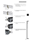
• Use solderless terminals when wiring the terminal block of the power supply part. To prevent short-circuit
that may occur when a screw become loose, use a solderless terminal with insulation sleeve, of which
thickness is 0.8mm or less. Up to two solderless terminals can be connected to one terminal block.
• Use UL-approved solderless terminals and, for processing, use a tool recommended by their manufacturer.
• Tighten the terminal screws on the power supply part within the applicable torque range of 0.66 to 0.89N•m.
• Use the following wires for connection to the power supply part.
Applicable wire size Material Temperature rating
0.75 to 2mm
2
(18 to 14AWG) (stranded wire)
Copper 75°C or higher
NZ2GF-ETB
FG
LG
INPUT
AC
24V DC
AC
DC
+24V
24G
Ground wire
Grounding
Terminal block
Solderless terminal with
insulation sleeve