


37
CHAPTER 3 SPECIFICATIONS
3
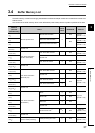
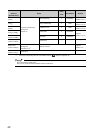
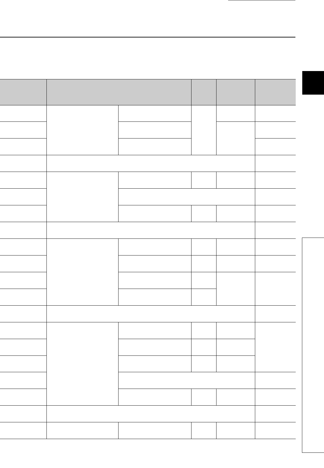
3.4 Buffer Memory List
3.4 Buffer Memory List
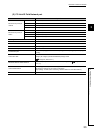
The buffer memory is used for exchanging data between the Ethernet adapter module and a master/local module or an
external device.
The contents of the buffer memory return to the default state (initial values) when the system is powered off or reset.
Address
(Decimal
(Hexadecimal))
Name
Initial
value
Read/Write Refer to
0
(0
H
)
Module operation area
Module LED information
0
Read
Page 201,
Appendix 1.1 (1)
1
(1
H
)
Station No. LED information
Read
Page 201,
Appendix 1.1 (2)
2
(2
H
)
Ethernet port LED information
Page 201,
Appendix 1.1 (3)
3 to 15
(3
H
to F
H
)
System area
16 to 18
(10
H
to 12
H
)
Own station information
(PORT1 and PORT2)
Own station MAC address Read
Page 202,
Appendix 1.2 (1)
19
(13
H
)
System area
20 to 21
(14
H
to 15
H
)
Own station IP address 0 Read
Page 202,
Appendix 1.2 (1)
22 to 25
(16
H
to 19
H
)
System area
26 to 28
(1A
H
to 1C
H
)
Own station information
(Ethernet port)
Own station MAC address Read
Page 202,
Appendix 1.2 (2)
29
(1D
H
)
System area
30 to 31
(1E
H
to 1F
H
)
Own station IP address 0
Read
Page 202,
Appendix 1.2 (2)
32 to 33
(20
H
to 21
H
)
Own station subnet mask 0
34 to 35
(22
H
to 23
H
)
System area
36
(24
H
)
Own station information
(Parameters)
Mode 0 Read
Page 202,
Appendix 1.2 (3)
37
(25
H
)
Network No. 0 Read
38
(26
H
)
Station No. 0 Read
39 to 47
(27
H
to 2F
H
)
System area
48
(30
H
)
Function check area
*1
0001
H
Read
Page 202,
Appendix 1.2 (3)
49 to 767
(31
H
to 2FF
H
)
System area
768
(300
H
)
Ethernet port operation area
(area for initial processing)
Initial processing error code 0 Read
Page 203,
Appendix 1.3 (1)