Director
9
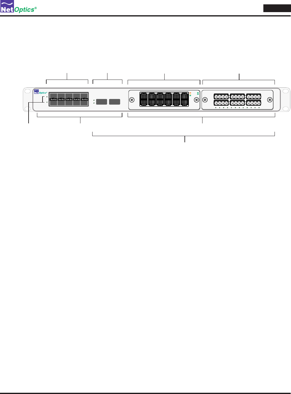
Director Front Panel
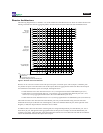
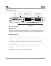
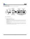
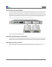
The features of the Director front panel are shown in the following diagram.
www.netoptics.com
™
Director
1
2
B
A
1
6
2
7
3
8
5
10
4
9
A B
In-Line
10/100/1000
10
100
1000
LINK
ACT
In-Line
GigaBit
1 2 3 4 5 6 7 8 9 10 11 12
A B A B A B
10 SFP
Monitor
Ports
2 XFP
Configurable
10GbE Ports
2 Director Network Module (DNM) Slots
DNM with 10/100/1000
Copper Network Ports
(6 In-line or 12 Span Ports)
DNM with SX Fiber
Network Ports
(6 In-line or 12 Span Ports)
Monitor PortsPower LEDs
Network Ports
Director Front PanelFigure 6:
Monitor Port LEDs
Each Monitor port has two light-emitting diode (LED) indicators. The Link LED is illuminated when a link is estab-
lished. The Activity LED blinks when trafc is passing through the port. They are located in the middle between the
two rows of SFPs.
DNM / Network Port LEDs
Each 10/100/1000 Network or Span port has two LEDs. The Link LED is illuminated when a link is established. The
Activity LED blinks when trafc is passing through the port. The Link LED also indicates the link speed: amber for
10Mbps, yellow for 100Mbps, and green for a 1000Mbps (1 Gbps). They are integrated in the RJ-45 connectors, Link
on the left and Activity on the right.
Each 1-Gigabit Fiber Network or Span port has a single LED. It illuminates solid when a link is established, and it
ashes when trafc is passing through the port. These Link LEDs are located below the LC ber connectors.
10 Gigabit Port LEDs
Each congurable 10-Gigabit port has a single LED. It illuminates solid when a link is established, and it ashes when
trafc is passing through the port. These Link LEDs are located to the left of the XFP ber connectors.
Power LEDs
Two LED indicators for power, one for each of the redundant power supplies.


