


October 2006 1002rp server description
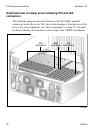
1002rp Server Hardware Installation 19
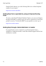
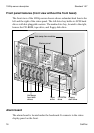
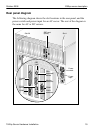
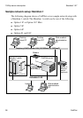
Rear panel diagram
The following diagram shows the slot locations in the rear panel, and the
power switch and power input for an AC server. The rest of the diagram is
the same for AC or DC servers.
G101648
Power
switch
Power
input
Slot 20
SBC card
(slot 8) Slot 1
SBC
card
COM2
CLAN
connector
PS/2
Keyboard/
Mouse
Monitor
connector
Parallel
port
ELAN
connector
COM1