


Installing the server and connecting the peripheral devices Standard 1.07
66 CallPilot
To connect the mouse, keyboard, and monitor to the
server
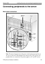
1 Place the monitor, keyboard, and mouse in the same location as the
server.
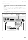
2 Plug the keyboard/mouse dual cable into the PS/2 connector on the SBC
card faceplate (see “Rear panel connectors” on page 65).
3 Plug the keyboard and mouse into the appropriate connectors on the
keyboard/mouse dual cable.
4 Plug the monitor into the monitor connector on the SBC card. Tighten the
screws on the connector.
5 Ensure that a single-point ground reference is available for all the power
outlets serving the CallPilot server and its peripherals. Before the
CallPilot server installation, a qualified electrician must implement the
single-point ground reference requirement between the power outlets of
the CallPilot server and the power outlets of the switch.
6 Connect the power cord to the monitor and plug the other end into a wall
receptacle or power bar.
Note: Ensure that the power source is consistent with the SBC for all
ancillary equipment.
7 Turn on the monitor.
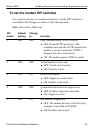
To connect the modem to the server
1 Ensure that the modem AC power cord is not plugged in.
2 Connect the large 25-pin male connector to the back of the modem.
Tighten the connector screws.
3 Connect the 9-pin female connector to COM1 at the rear of the server.
Tighten the connector screws.
4 Connect one end of the telephone cable to the modem RJ-11 jack
labeled LINE.
5 Connect the other end of the telephone cable to the RJ-11 jack in the
wall.